PCB and Wiring
A PCB from another source can be used in replacing the electronics in a standard device, or giving communications to a custom controller.
The simple goal in wiring is to have the grounds and signals of each device (like joysticks and buttons) linked to the ground and desired corresponding signals on the PCB. Each device has switches; when the switch is engaged, a circuit between the ground and signal should complete and send the signal from the PCB through a cable or remote to the computer or console. Wires and connectors, solder, and/or twisting are used to link the devices to the PCB.
For quality PCB wiring, the main goals are having required signals covered by the PCB, corresponding ground and signal connections and circuits, solid and secure connections, connections that will not cross or interfere, insulation, and some level of organization.
While this wiring concept is simple, implementing it and enhancing it can be more difficult as you can see by the size of this section.
Contents
Electricity and Grounds and Signals
Lines and Connectivity
PCB Attributes
Lag
Wired Vs Wireless
Custom PCBs
Extracted PCBs
Soldering
PCB Mapping and Soldering
Solderless Extracted PCBs
PCB Components Modification and Removal
Converters
PCB Diagrams
Wire
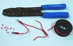
Terminals and Crimping
Twisting
Splicing and Chaining
PCB Mounting
Joystick Connection
Cable Modification
Terminal Strips and Organization
Multiple PCBs
Electricity and Grounds and Signals
In order to understand the function of a ground and a signal in a switch and its device, you have to understand a few things about electricity.
For electricity to do its work, it has to flow; the movement of electrons (mainly) is what gives electricity its effect on things. In order to flow, electricity needs an entry point and an exit point, and there has to be a difference in the density of electrons (the charge) between the entry point and the exit point. Electrons flow quickly from an area with relatively more electrons to one with relatively fewer electrons in order to establish equilibrium (this density mainly depends on the number of electrons per atom compared with each atom's atomic number).
Voltage describes the density of electrons (the charge) in one object compared with that in another; voltage is a comparative rating requiring two areas to have any meaning (but often the term voltage is used like the term charge). The flow of electricity from one charge to a different charge is where signals and the ground come into play. Voltage has no bearing without two separate areas, so without two areas, there is no voltage, and no work can be done by the electricity. Relatively higher charge is described in terms of being positive with a positive sign, while relatively lower charge is described in terms of being negative with a negative sign.
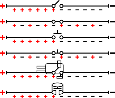
Image: The flow of electricity and switches and button engagements (not the exact design for a microswitch)
In controllers, unique electronic signals are used to turn the pressing of switches into unique commands used by the console or computer. The term signal is used to describe the unique sites (with unique electric attributes) that produce each command. In most circumstances (but definitely not all), signals use higher voltage and can be regarded as the positive charge.
The counterpart for the signals is usually (but definitely not always) a ground. Grounds have what is regarded as a neutral voltage, described as 0 volts. Grounds are often made by burying large metal plates accessed by connected wires in the ground (hence the name). The ground has a fairly universal charge (the charge of the Earth) and voltage is produced by giving objects a charge different than the ground. Since the ground usually has the relatively lower voltage, it usually gets regarded in terms of being the negative. Other grounds are functionally produced within batteries which contain two areas with a different charge (though they are usually just regarded in terms of having a positive and a negative and not a ground).
Since the ground has no unique attributes and signal charges can all be dumped in the same place, usually the same ground (called a common ground in this case) gets used by various signals. In this configuration, signals are recognized as engaged when their charge is flowing into the ground, and are recognized as disengaged when their charge is not flowing.
A circuit is basically a connection between different charges; because otherwise a circuit does not have a function, one or more electronic components (like a switch) must be along this connection for it to qualify as a circuit. Making simple circuits involving switches is at the heart of making a controller function; one terminal of each switch connects to a signal, and another terminal connects to a ground (or sometimes something different that functions similarly). When a switch along a circuit is not engaged, the switch and circuit is open (not completed) and no work is done. When a switch is engaged, the switch and circuit is closed (completed) and work is done by the electricity, engaging a command.
Lines and Connectivity
Much of this subsection may seem obvious, but some points need to be made and some rules established.
A conductor allows electrons and electricity to flow through it; strong conductors especially include metals like copper. An insulator allows pretty much no electrons and electricity to flow through it; some insulators include glass and many plastics. And a semiconductor is a specialized arrangement of materials that can function as an insulator in one situation, and a conductor in another; semiconductors are especially made from silicon.
Wire is a conductor formed into a thread and often covered with an insulator. A trace is a conductor printed in paths on an insulated board. Since wire and traces are lines of conductive material, they function the same way for the most part. Lines of conductive material are how electricity is distributed and connected. Connectivity is important in electronics in helping to understand and implement designs; in electronic diagrams, connectivity is drawn using lines that usually do not resemble the actual device, but functions the exact same way.
Under the attributes of electricity commonly used in PCBs and wiring, electricity will only travel through conductors that are in direct contact, and will not jump the way static and high charges of electricity can. Conductors make direct contact when they touch each other like with the shaping of a single piece of material, soldering, and pressing together (like openly or with a switch, crimp, or twist). Note the extremely detailed PCBs used in microprocessors; they have unique traces that are within very tiny measurements of each other, but still function individually. Only when atoms of a conductor are in direct contact are they electronically connected.
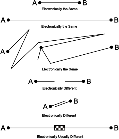
Image: Connectivity of lines
Electricity travels through strong conductors at a significant fraction of the speed of light. In terms of connectivity and electricity, any point along a line of touching conductive material is the same entity as any other point along the same line. The time difference between a charge hitting one point connected with another point across a room is comparable to 1/50,000,000 of a second. The varying thickness (like a trace with a tiny thickness connected to a thick wire) of connections has no effect in terms of being connected either. The terminal of a switch, connected directly to a wire, connected to a solder point, connected to a PCB trace, connected to another solder point, connected to the wire of a cable, connected to a pin, and connected to a trace in the PCB of a computer or console, are all the exact same electronic entity; anything that connects anywhere along this long line of connectivity will function exactly the same way.
Areas that are connected are often described as having a common line (sometimes described as just being common).
For the electricity used in a PCB, connectivity is all or nothing. A direct connection will never be slow. The electrons can either flow through the connection, or they cannot, never slowing down along the way. Either the connection functions or it does not. (Note though that thin connections can be inadequate or degrade in certain circumstances, though this is not usually trouble for the traces on PCBs.)
How the connections link electronic components is what is important. Generally, unless a component is a jumper, the lines of each end of the component will be electronically different because the component modifies the electricity in a desired way.
PCB Attributes
Circuits are at the heart of electronics. In order to compact, organize, and exploit many circuits, they are often printed on a board, making a printed circuit board, ie a PCB. Numerous and detailed conductive paths lay out the circuits and functions for a device.
Before PCBs were a standard of mass production, electronic components and wires were arranged on simple insulated boards sometimes containing holes. Perfboard is a sheet usually made of plastic or fiberglass with a grid of small holes, basically functioning as a wires and components mount (these are still used for designing and testing circuits); sometimes perfboard is coated with copper around each hole so components can be soldered to it. A PCB takes this concept, but uses a set design and prints conductive lines instead of wires (called traces) and solder points (for components) onto a durable board; often holes are drilled in specific locations for more durable connections; PCBs make it so components of varying and/or much smaller size can be arranged in a much more specialized layout.
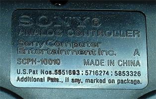
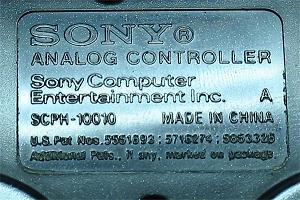
The bulk of most PCBs is made of a light, highly durable, nonconductive substance similar to fiberglass. On this another nonconductive layer (usually dark-green) that bonds well to metal is added. On this is added the conductive metal (usually copper) that makes up all the paths and points in the PCB. On the metal that does not need to be exposed, a nonconductive protective layer (usually light-green and called a solder mask) is added for insulation. On metal wanting to be insulated but still accessible, a conductive layer (usually black and rubbery) is often added (especially on button sites). Also printed in white is information about the maker and model along with numbered points with abreviations to indicate where individual components belong.
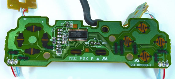
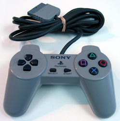
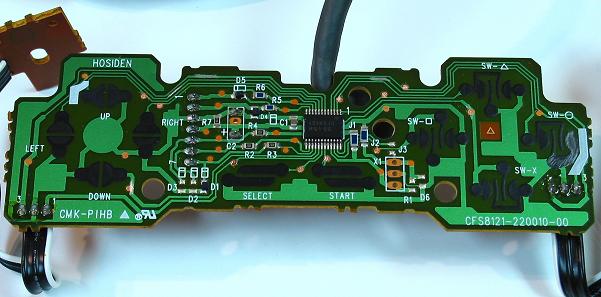
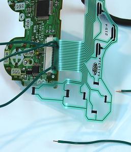
Image: Playstation 1 PCB
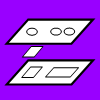
In older PCBs, usually only one side of the PCB is used. In newer PCBs, both sides are often used by adding small, conductive through-holes in the PCB. Double-sided PCBs have much more space for complexity and components.
Solder points are used to attach electronic components (which come in small bundles protruding from the board) to a PCB; these points consist of small open metal plates at the end of traces. Solder is a metal glue used to bond the metal ends of components to solder points. Larger components that extend from the PCB (like the wires for a cable) use stronger solder points with larger plates and holes to fill. Various components like the processor (the large black chip with legs, also called a chip or an integrated circuit), resistors, capacitors, transistors, diodes, and oscillators enhance the function of the PCB; components are placed in different locations between the ends of two or more PCB traces.
For game controller PCBs, at least three wires make up the cable. Each wire terminates in the pins in the plug at the end of the cable; not every pin is always used, and some wires can lead to multiple pins. One wire is the higher charge (the source of voltage, usually about 5 volts), one wire is the ground (which is 0 volts), and one or more wires are data (which sends and/or receives commands). Other wires do things like syncronize the controller with the computer or provide even higher voltage (around 10 volts) for some rumble motors.
One line of the voltage (the source of a higher charge) and one line of the ground lead to the processor to make it function. Voltage is usually distributed to many unique legs of the processor for each signal. Lower voltage (from the ground) is usually distributed to one of the legs on the processor. In most PCBs, the ground connection also establishes a ground common to all the buttons (described as a common ground). But in more complicated PCBs, more ground lines create multiple grounds common to individual or groups of buttons; in fact, the term multiple grounds does not make sense as there is only one ground, and lower voltage sites called common lines, or just commons, are established; sometimes some signals will use the ground, while others will use commons, and sometimes commons will have higher voltage than their corresponding signals.
The processor also connects to the data line(s); when a signal line makes contact with the appropriate ground line (like when the switch in a button is engaged), the property of the electricity flowing in the data line(s) is altered to send the appropriate command.
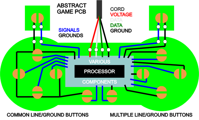
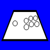
For control pad PCBs, the signal and ground legs on the processor are distributed through traces (which often go through various components) leading to sites for the base of each button. The sites for the base of the buttons usually consist of a conductive circle divided into equal halves; the signal trace connects to one half, the ground trace to the other. Grounds (and commons) are recognizable because single ground traces lead to halves for multiple button sites. The base of each actual button in the control pad has a flexing conductive node; when the button is pressed, the conductive base makes contact with each half, connecting the signal to the ground, engaging the button and sending the command; this is how the button sites act as switches.
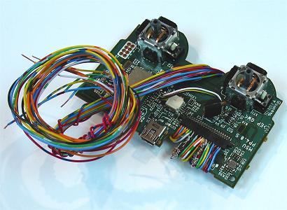
For PCBs used in larger devices (like a joystick control panel), the layout is usually more compact and organized; the PCB is not made relative to the size of the panel; wires extend from the PCB to switches away from the PCB. Instead of having button switch sites, usually larger solder points for connecting signals and grounds (not in pairs) are arranged in a row like they are for the cable. Custom PCBs also usually have these attributes. Making a PCB designed for a control pad function in a joystick controller is simillar; wires are attached to proper lines and extended to the switches in the joystick and buttons.
The exact functioning of various components (especially capacitors) on PCBs is not too important in using a PCB in a controller. Average use of a PCB simply involves connecting wires to the signals and grounds on a PCB, and linking those to the terminals on switches. PCB diagrams can make this especially easy. Never remove any components from a PCB without understanding how it can impact its function; even the removal of the tiniest component can cause the PCB to fail (though they can often be replaced with soldering). Some simple things that can be removed without harming the PCB include the rubber button bases, the plastic caps on analog sticks (not the base functioning part), the battery (if the PCB is plugged in), and rumble motors.
For more advanced work on a PCB, some understanding of some electronic components is needed. The benefits of component work include making the PCB more compact, using tricky trigger buttons, making commons use the ground, making a single button engage multiple buttons, adding LEDs, adding toggle switches, and many other creations. The later part of this section covers some of this topic, and is much more complicated, but is not necessary in building a controller; these things will not make the PCB function faster or more accurately. Knowledge of soldering will also be required for this work.
There is a choice to be made between extracted PCBs and custom PCBs as well. Most custom PCBs are designed to be very user friendly, being very easy to install, not requiring so much experience or knowledge. Knowing how to use extracted PCBs and how to solder will give more options, including making your controller compatible with more consoles and giving less expensive alternatives.
Lag
Latency is a term describing the time between data being sent (or engaged) and being received. Lag is a term describing a latency that is less than adequate (though it can often be used as a synonym for latency; sometimes in data input the term response time is used). For gameplay, lag is a huge performance issue; it determines who gets commands in first, and how fluidly a player interacts with a game.
There are many sources of lag in gaming:
- In internet play, there is an inherent physical lag in transmitting signals over geographic distances (the bigger problem here actually tends to be passing through more servers).
- Computers and communication lines can take time to process and transmit data, especially when a great deal of data needs to be processed in a short period of time (servers are especially vulnerable to this); this can be treated by upgrading structure and software (like finding a better bandwidth); elsewhere, when computers are designed properly, this should not be a problem.
- Network security protocols can add more processing time as they encode and decode and verify large pieces of data; this can be helped by getting a quality router, either disabling wireless securities or just using wires on the router, and by disabling firewalls (disabling some are not a good idea on PC, but all are okay for consoles).
- Newer retail televisions (especially HDTV ones) have complex components that process images before displaying them; different models of televisions perform better in term of lag than others (called input lag or input delay); computer monitors can even have a bit of lag; unfortunately manufacturers currently rarely list input lag; the best option to counter this is to research displays to find ones with very little reported input lag; the next best options (which still lag a bit) are to use the Game Mode settings many televisions have, and to connect using the VGA port (an adaptor can help with this); the measurement called response time in monitors (especially LCDs) mostly measures the blurring of moving pictures and has very little to do with lag (though it can also be bad for gaming).
- Computers often use vertical synchronization (v-sync) to improve images; this can lag input up to one frame, and can be disabled (though the image will likely have lower quality).
- Because of poor electronic design, game controller PCBs and converters can lag; research to find ones that do not lag; most first-party controllers do not lag.
- Converters for controller PCBs can also lag much like poor PCBs do.
- Some electronic components like diodes, transistors, and integrated circuits each lag very slightly (around 5 to 100 nanoseconds).
Lag and latency are usually described in terms of milliseconds (1/1000 of a second) and frames; in most gaming, there are usually 60 frames in a second (many PAL games run at 50 frames; this has a lot to do with the frequency of alternating current electricity used in different world regions); in terms of milliseconds, 1 frame usually equals 1/60 of a second, or 16.7 milliseconds. When gaming does not involve the internet, total lag should not be greater than one frame. Do not use PCBs, converters, systems/computers, and/or televisions/monitors that have any reported problem with lag.
First-party controller PCBs (which are made by the same company who made the console) rarely lag (one exception is the official Dreamcast controller PCB), and tend to be more compatible with converters, which is why I tend to recommend them over mystery PCBs; many (but definitely not all) third-party controllers have lag, so do homework before using one.
Other noteworthy lag comes from the Playstation 3 running Playstation 1 and 2 games; a Playstation 3 running backward-compatibility lags 3 frames. Unfortunately, it is better to play Playstation 1 and 2 games on the Playstation 2.
Wired Vs Wireless
In wireless controllers, a voltage and a ground is provided by a battery, while data is sent through the air in various ways. In both these areas (especially data transmission) wireless controllers have come a long way. Because of this, many first-party controllers are now wireless.
In the past, many wireless controllers functioned using infrared LEDs, which is what most remote controls have used as well. The signal from an LED is very disruptable as it gets blocked or muddled in many ways; and many of these setups produce a lot of lag. Because of this, wired controllers have historically had a much better performance.
Newer wireless controllers use Bluetooth which functions using dense radio signals. A great deal of data can be transmitted and processed very quickly using Bluetooth. Plus, it is difficult to block or disrupt the signal; it can go through materials like wood, plastic, and even metal; do not worry about Bluetooth signals getting blocked. With these attributes, the difference between wired and wireless controllers using newer wireless technology is pretty much negligable.
Nintendo Wii, Xbox 360, and Playstation 3 wireless controllers take advantage of the newer technology. Also note there is an adaptor that allows Xbox 360 wireless controllers to work wirelessly on PCs (it is currently out of production though). For past generation systems, you will not likely find this new technology. With other wireless controllers, check for performance or technology attributes.
Custom PCBs
Custom PCBs can save a lot of time, are much more simple, and often do not require soldering. Many are designed specifically for use in control panels. Most of these specially made PCBs cost a little more and are made for PCs (often more expensive converters are available). Currently there is an exception in some PCBs designed by Toodles, especially the Cthulhu PCB. I have a lot of praise for the work of Toodles in this subsection, but it is not because I want to advertise for him; there just really are not products I know of comparing to his at this time.
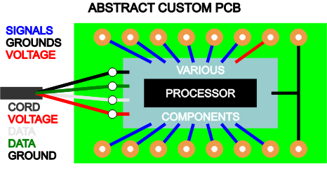
PCBs used in larger controllers are usually designed with a layout much more symmetric and smaller than PCBs from control pads. A processor surrounded by various components and branching traces is still usually at the heart of custom PCBs. But instead of button sites, large solder points are usually spaced individually (not in common pairings) along the sides of the PCB. Custom PCBs usually use a common ground; this common ground can be distributed to each signal for all the switches. PCBs used in brand joystick controllers are very similar to custom PCBs, but usually less user friendly.
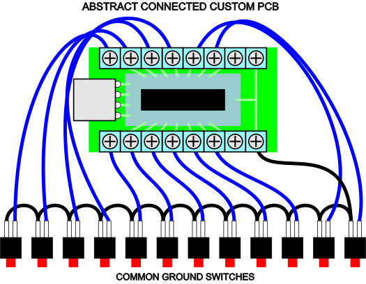
Many custom PCBs come with terminal strips and a USB connector. The terminal strip is a PCB-mounted version that will hold down wires in connection to the solder points using a screw for each point. The USB connector makes it so the cable can be attached and detached easily. Along with the small even layout, these features make using custom PCBs usually much easier than extracted PCBs. Since pretty much all custom PCBs use a common ground, one wire has to be linked from the ground to one terminal that gets chained to the other terminals, and the remaining wires link signals individually to each button or joystick or other device switch.
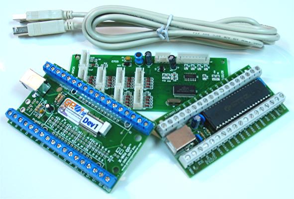
Image: Left to right: KeyWiz-ST (its cable too), X-Arcade PCB, I-PAC VE
Ultimarc (based in the UK) produces the I-PAC and other variations of it. It has terminal strips (European-style) built into the PCB. It also has software to alter the button settings. It comes based for PC, but converters are available from them. (link)
Groovy Game Gear (based in the US) produces the Key-Wiz and other variations of it. These PCBs are very similar to the Ultimarc versions. (link)
X-Arcade sells the PCB used in their controller alone, though a bit expensive. Avoid this PCB because it lags and does not have a common ground (though I hear they are working on making a better product). It comes with ready-made wiring using only .187" terminals. (link)
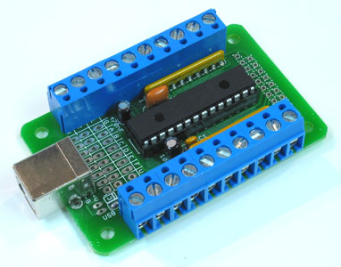
Image: Cthulhu PCB
The Cthulhu PCB designed by Toodles works for the Playstation 3 and PC when a USB cable is attached. Thanks to his programming of the processor, it also works for the Gamecube (and Wii), Xbox, and Playstation 1 and 2; all that is needed is a cable from each system and some diodes; when the wires in the cable are connected to the appropriate solder points on the PCB, the processor senses the proper system, and sets itself to send the proper signals. The various cables also work with standard converters (like Playstation to Dreamcast). The back of the PCB has ports that can be used to attach other PCBs (with a common ground) to work along with it. It comes with instructions on how to set these things up. If you would rather not learn soldering, and do not need to set other electronic components up, the Cthulhu board is a great option; otherwise, it is still a great option. (link)
The other PCB designed by Toodles is the UPCB (Universal PCB). It is a predecessor to and much more complicated than the Cthulhu, requiring at least some soldering to use. It is the most versatile game controller PCB around, functioning individually on almost any mainstream system (again using other cables), excluding the Dreamcast and Xbox 360. Dreamcast PCBs have unique wiring (best to use converters); Xbox 360 PCBs use a special security chip designed by Microsoft; these PCBs can be attached to the UPCB. The UPCB is more advanced, though Toodles instructions are very thorough; if you want to get more hardcore with the PCB design, look into the UPCB. (link)
Extracted PCBs
The goal in extracting a PCB from a device is to modify it to work for another instrument.
The drawback to using an extracted PCB is that it will usually require soldering with more permanent and complex steps in building your controller (sort of excluding some Playstation PCBs discussed in the solderless subsection), and it takes more time and experience than using a custom PCB. The upside is you can easily choose the system for which your controller is designed (there currently is no custom Xbox 360 PCB), get better converters, and maybe save a bit of money. (Again, it should be noted that there has been strides made in improving custom PCBs, namely those designed by Toodles.)
Find a device like a keyboard or gamepad (preferably) with the compatibility and at least the number of commands desired (one for each button, four for the joystick).
I do not recommend going through the trouble of using keyboard PCBs unless you are already very familiar with modifying them. Many keyboard manufacturers specifically design their PCBs in a way that makes exploiting them for other things difficult. Keyboard PCBs can have problems with sending multiple signals close to the same time called "ghosting" (you can be familiar with this by the reaction your computer gives you when you mash keys) and may require some extra work to function properly. Plus it can be difficult to distinguish game commands from standard keyboard commands on your computer. PCBs from game controllers are much easier.
For gamepads, find a good system (or two) to use in your controller; converters have a large bearing on this choice, as explained in the converter subsection. As for which model of gamepad to choose, there are trade-offs to using a first- or third-party devices, and even different models of those.
First-party devices, made by the same makers of the console, generally have great performance with the machine for which they are designed, but often are more expensive. Third-party devices, made by independent makers, can sometimes have performance problems, but are usually less expensive; an example of this is, due to complex formatting, many third-party wired Playstation 3 controllers have a flaw that does not allow the left direction to engage for more than a few seconds.
Third-party devices can also be more delicate. Often, a much thinner, more fragile layer of metal is used on the PCB (if the PCB is not damaged during modification, this is not a problem), and the wires in the cable are often thin and fragile. Some makers (like Intec) also intentionally make their controllers very difficult to modify. And first-party controllers tend to have better compatility and performance in using converters. For these reasons, it is a good idea to either use a first-party device, or make sure a specific model of a third-party device works well.
Plus different models of PCBs are easier to modify than others. Some have larger and/or more open button sites than others, and other special things that can make them more easy or difficult. Many aspects of this are discussed in this section, especially in the PCB diagrams subsection.
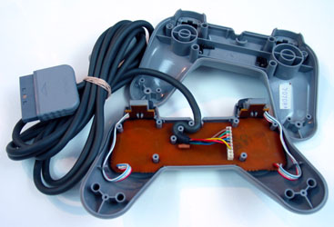
Images: Simple, yet very practical, controller; Controller opened
A used or even broken controller will also work fine as long as the PCB (which is pretty much sealed) and cable or remote are fine, so check old controllers or local game stores or trading websites.
When extracting the PCB, make sure not to disturb the board(s), the wiring between the board(s) and cable or remote, and the cable or remote itself; these are the things you need. Undo all the connections that hold the device together (usually just screws on the back on the controller) before opening it up; sometimes some screws will be under stickers. After carefully separating the casing, there may be more screws holding down the PCB inside the casing; remove all screws on the inside and carefully slide the PCB from the case. Note that wires connecting rumble motors, a battery, and third-party cables seem to be especially fragile in game pads.
Soldering
Solder is conductive metal that melts at a relatively low temperature and is used to bond two or more metal surfaces; it can be described as conductive, metal, hot glue. Solder does not bond things that are not made of metal. A solder connection is more often called a solder(ed) joint. In regards to a controller, it can be used to bond wire ends to metal spots on an extracted PCB and/or switch terminals on devices like joysticks and buttons, electronic components, and even crimping terminals.
Solder is made of a mixture of lead, tin, and sometimes silver and/or copper. Lead-free solder does not have the lead (increasingly popular because lead can be bad for the environment); if a solder product does not say it is lead-free, assume it has lead. Solder can be used to bond metals including lead, tin, silver, copper, zinc, and alloys containing a signficant portion of these metals (like brass). It can also be used to bond other metals, but often more complex procedures are needed (unless you are already familiar with soldering other metals, I recommend not bothering).
Soldering is not the same as welding which melts two metal objects together without an added intermediary (solder) using very high temperatures not feasible for sensitive electronics. Brazing is a medium between soldering and welding, basically a high-temperature soldering, also not feasible for electronics.
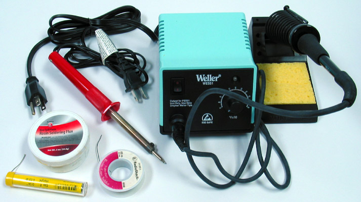
Image: Lead-free solder in a dispenser, lead-containing solder in a spool, flux paste, cheap soldering iron (red), and soldering station with temperature adjustment and stand
Soldering takes a bit of practice. It is not as simple as melting things together. There are a few complicating things. As with other tools, I recommend looking up a video of a professional soldering along with studying the process as described in this subsection. Also like tools, use safety practices such as avoiding awkward positions, rehearsing movements, avoiding potential obstructions in your surroundings, using a lot of light, and perhaps wearing some thin gloves and/or safety glasses.
For solder to bond to a metal surface, the surface also needs to be heated. There is a very slight welding of the solder to the surface of the metal. Soldering irons actually are not specifically designed for melting solder, they are for heating surfaces so the surfaces can melt the solder. Soldering works best when metal surfaces are heated and the solder is melted on those heated metal surface. When molten solder comes in contact with a metal surface that is properly heated, it attracts to it like a magnet. A good solder connection should hold like strong glue.
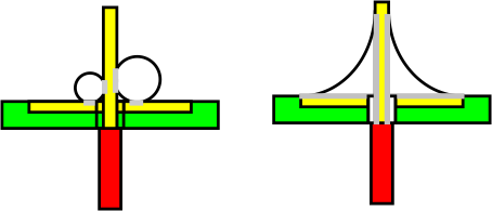
Image: Weak solder connection due to oxidation or lack of heating (left), strong connection (right)
Adding a very small bit of solder to the tip of the iron gives it a medium to transfer heat from the soldering iron to the metal surface (this is called wetting). For pretty much every soldering practice, the tip of the soldering iron should be at least slightly wet (including desoldering).
The main difficulty in soldering is oxidation. Oxidation removes electrons from metal particles; this does two negative things in electronics soldering. It makes metal less conductive. And it makes solder and metal surfaces not adhere as well. Oxidized metal looks dirty and dull. Oxidized solder is dull (though cheap lead-free solder always is) and more white, and is not cohesive or adhesive. Unfortunately, oxidation occurs at a substantially faster rate when metal is heated.
Oxidation is fought in a few ways. If oxidized (dull), the surfaces of the metal need to be cleaned before soldering using abrasives like steel wool, sandpaper, or scraping using things like the head of a wire or a craft knife. If it is dirty, it needs to be cleaned using a cloth perhaps damped with some rubbing alcohol.
The main oxidation fighter in soldering is flux. Flux removes oxidation when it is heated into metal. One main flux substance is rosin (hence the use of rosin-core solder; rosin flux can be obtained by itself and is sticky). You see the flux when you melt fresh solder and smokes emerges; the smoke comes from the flux. Fresh rosin-core solder or flux added to old solder can also help remove oxidation. When working with oxidated metal, you can often see it take on that magnetic quality once flux has been heated into it.
As you can see when you melt solder, the flux (smoke) only lasts so long (usually about 15 to 20 seconds of heating removes all the flux, though noticable smoking ends much earlier). This introduces another fighter of oxidation: speed. The solder and the metal surfaces should be heated for as little period of time as possible. As a general rule in soldering a PCB, the surface should not be heated for longer than about 8 seconds, and more like 4 seconds for stronger soldering irons; less time will produce better results. This is also why adding solder to heated surfaces instead of the soldering iron is important; the much hotter iron tips burns away flux much quicker than the heated surface, and the solder is heated much longer when waiting for a surface to be heated. Long heating can also damage things like thin traces and sensitive components like transistors and integrated circuits; attached alligator clips can absorb some of the excess heat.
Solder usually takes about three seconds to go from a liquid to solid state. Wait at least about five seconds to move solder joints after removing heat.
There are many objects that can go into a solder connection: two or more metal surfaces, solder, and a soldering iron. You only have two hands and should not try stunts to hold many things at once. Use things like clamps and alligator clips or helping hands to hold surfaces, and techniques that fit working with two hands. The soldering iron can also be secured in an accessible place and objects brought to it.
With these concepts in mind, there are two main methods for soldering. In each the soldering iron needs to warm to a high temperature beforehand.
The first and more difficult technique involves placing the two metal surfaces in their final position, holding the soldering iron in one hand and the solder in the other, and heating both surfaces while adding the solder. Be sure the iron is wet and that both surfaces are heated at the same time to reduce the time needed to add solder.
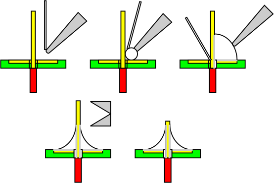
Image: Soldering all surfaces simultaneously: the soldering iron is wetted, the iron is applied to heat both surfaces and solder is added to one side, solder is applied to surround the connection, excess is cut away (this is best done with diagonal cutters)
The second and easier technique involves placing most of the needed solder on each metal surface (this is called tinning) and then melting them together with the soldering iron in one hand and one of the surfaces in the other. Tinned surfaces generally take solder connections easily. The downside of this technique is slightly more oxidation occurs since the overall heating time will be a bit longer. However, this is usually the best technique in adding wires to button nodes on a PCB since mounting holes are often not available. Note that the wire can get hot near where it is heated; try not to hold it within about 4 inches (100mm) of where it is heated, or wear a glove or use a rig like helping hands.
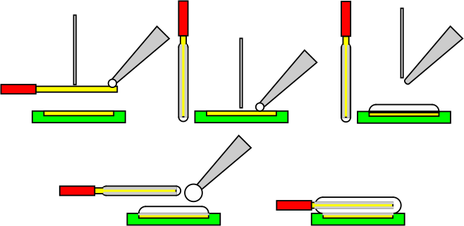
Image: Soldering in individual steps: half the needed solder is heated to one surface, the other half is applied to the other surface (both cool), the soldering iron is wetted (with more solder than usual), the two are melting together
Another technique that is a hybrid of these two techniques is putting solder on only one of the surfaces and the tip of the soldering iron and quickly heating the surfaces together. This technique may be preferred, but, besides a small amount of saved time, it does not really have an advantage over the double-tinning technique.
Do not solder objects while they are plugged-in as this can damage either the PCB or the soldering iron (especially irons with anti-static features).
Solder usually comes in spools of bare wire. Since PCB work is small, be sure to use thin solder wire between about .02 and .04 inches in thickness (0.5mm to 1.0mm). Solder also comes with or without rosin-core (flux-core). You can choose flux-free solder, but you will need to add flux to make the solder bond (it does not bond without it). Excess flux needs to be cleaned (rubbing alcohol works well) after soldering is done or it will cause corrosion. I tend to prefer rosin-core solder because flux is sticky and cleaning is not necessary when using it; if experienced with soldering, rosin-core solder should have plenty of flux. Varieties of solder containing other types of flux (along with other types of flux) are not appropriate for electronics work.
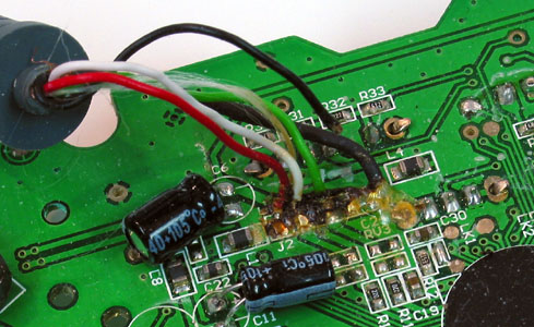
Image: Corrosion around the cable connection resulting from flux not being cleaned after soldering
There is also a variety of soldering irons with different attributes. The simplest and least expensive irons regulate their own level of heat and are rated based on wattage; these tend to have about the same level of heat, while the wattage rates how much material can be heated in a given amount of time; for these simple irons, 15 to 45 watts is appropriate for electronics work, though I tend to recommend 15 to 30, especially 25 or 30 (generally the lower the wattage, the less likely significant mistakes will occur). More expensive soldering stations feature things like a separate power unit giving faster warmup times, antistatic, quality automatic feedback adjusting and readouts, thinner and lighter soldering pencils, and wattage or temperature adjustments; temperatures of about 250 to 400 degrees celsius (480 to 750 fahrenheit) are appropriate, with the higher range more appropriate for lead-free solder.
Other soldering irons use burning gas or powerful shocking to heat solder. I recommend avoiding these for electronics work, but gas irons and torches can help in soldering solid pieces of metal.
There is also a varieties of bits (heads) for soldering irons. Look for tips with a small head that tapers slowly down the bit in a cone shape for small PCB work. Most really inexpensive soldering only have one tip designed for them.
To keep the tip of a soldering iron clean, a damp sponge helps. Simply rub the tip of the iron across it, when it is hot or cool. The sponge should be used to remove the accumulation of burnt flux and other contaminates. A sponge should not be used specifically for removing wet solder since it actually helps in reducing oxidation by leaving a small amount on the tip of the iron; after using a sponge to clean the tip, add a bit of solder to the tip again; it is a good idea to clean then wet the iron before leaving it idol. More abrasive things like steel wool and braid can help remove stronger contaminates. It is not a good idea to rub the tip of the iron too hard as this can remove special coatings. Also avoid having the iron melt things besides solder (like wire insulation or glue) because they can mend strongly with the tip.
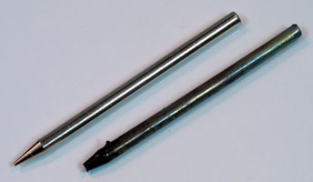
Image: Soldering iron tips, same model, one new, one after extensive use
Iron tips do wear out, and make setting clean and accurate solder joints very difficult; often it is best just to replace them when they start functioning poorly. Though new tips come pre-tinned, try to tin new tips quickly when they are heated for the first time to avoid base oxidation.
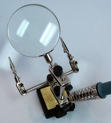
Image: Soldering stand with helping hands
Soldering stands feature a heavy and/or wide base with an area to hold a sponge and a coil to hold a soldering iron. Better quality versions have an insulated rim at the top of the coil so the iron does not lose heat.
Helping hands feature secured and adjustable alligator clips. These are great for holding PCBs and wires in helpful positions. I tend to recommend having a separate stand from the helping hands; having both together can be a bit awkward.
There is a high chance in learning to solder you will get burned a few times. Treat burns with cool (not cold) water and maybe some ointment and bandaging. Remember to be organized, not to touch any metal on the soldering iron, and that heat transfers (do not hold objects near where they are being heated). Consider getting a soldering station to make things easier; a station can also extend the life of the iron and its head.
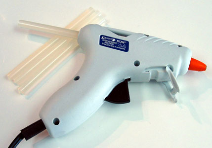
A good ally to soldering can be hot glue (most associated with glue guns). It does not conduct electricity and reinforces solder joints so they will not later break. This makes being gentle with the PCB not so necessary. Some other glues that are not conductive and designed for metal can also be used, but they cannot be removed with some warm air and peeling like hot glue. Usually, good solder connections hold well without glue, but smaller connections (like on thin traces), cheap PCBS, or heavier wire may need its help. Hot glue can also help hold a base of a wire to an unused part of the PCB to make it easier to get the wire held in the needed place before soldering, and give even more reinforcement.
Desoldering
More difficult than adding solder is removing it.
For simple controller builds only involving adding and removing single wires, knowing how to desolder is not all that necessary since solder really does not require removal. Wires can be removed simply by heating the solder joint and lightly pulling the wire away; a new wire can be replaced by adding some new solder so that oxidation is not a problem, and inserting the new wire (it should be tinned first) when the remaining solder is heated. Using all new solder tends to be better though. Note that the wire near where it is heated can get hot, so hold it far away from the heat, or wear a glove.
When it comes to making quality new joints, or having to remove a single object with several joints, desoldering is needed. Fresh, clean solder holds better. Things like variable resistors (triggers), analog sticks, and cables secured using a rectangular connector, have anywhere from three to eight to fourteen joints that all need to be loose to remove the component. It is possible with a 25+ watt soldering iron to lay the iron across the joints and pull a trigger or cable out, but this often results in damage or getting burned (use pliers to pull or the component).
There are two kinds of desoldering tools, braids and vacuums. There are three kinds of vacuums, bulbs and pumps and irons. There is also the option of flicking and blowing away hot solder; if the solder is thick enough, it can be flicked away when it is heat using the tip of the iron or another sturdy object that resists heat; a more dangerous and risky method heats it and blows it away with a compressor; both these techniques can often result in solder just being spread around; for these I recommend wear full clothing and gloves and safety glasses, but I also recommend using desoldering tools instead.
All desoldering techniques cannot remove all the solder. A thin layer of solder (a tinned layer) will always remain unless it is removed with an abrasive. Because using desoldering tools can take time, it is often a good idea to add some flux to the solder before trying to remove it (especially with desoldering braid; be sure to clean away excess flux after desoldering). Something that can help in desoldering is actually adding more solder to the joint to give a bigger target.
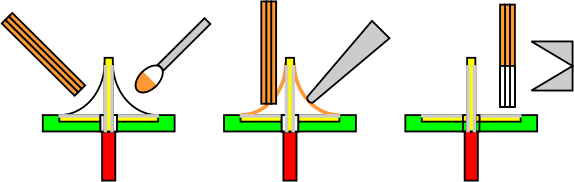
Image: Desoldering by submerging braid in heat solder: flux is added to the solder joint, the soldering iron is wetted and the solder joint is heated, then flux is submerged in the solder, it slowly absorbs the solder and is removed, then the iron is taken away
Desoldering braid consists of many very thin strands of copper wire wound together with a bit of flux; basically it functions as a hot solder mop. There are a couple techiques to using it. One technique involves heating the solder, then submerging the braid into, letting it absorb, then taking the braid away before taking the iron away; I tend not to recommend this technique because it uses a lot of excess heat. The second technique involves pressing the braid against the solder before heating, then heating the braid with the soldering around so that it absorbs solder, and maybe moving the braid around like a mop before removing them; I recommend this technique. With braid, it is best to have at least 25 watts in the iron, and make sure the iron is hot and wetted before beginning so heat will transfer better. Braid usually comes in special spools so that the spool can be held instead of the braid to prevent burning from transferred heat. Braid that has absorbed solder is cut away and disposed.
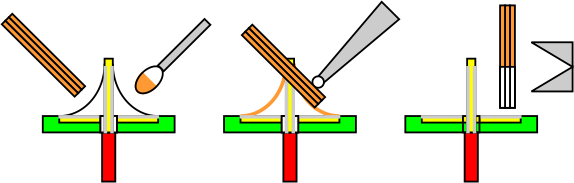
Image: Desoldering by heating braid on solder: flux is added to the solder joint, the soldering iron is wetted, braid is placed against the solder joint, then the flux is heated by the soldering iron, and both are removed at once after absorption of the solder
The most simple of the vacuum tools is the desoldering bulb. It is used by collapsing the bulb, applying heat to the target solder, placing the bulb's tip by the solder, and releasing. The biggest problem with bulbs is the tips tends to move all over the place when the bulb is expanded; this can be helped by propping the tip against the PCB before releasing; propping can help, but it still has troubles, and I do not recommend bulbs for this reason. Try not to collapse the bulb again quickly following the suction of solder as it can shoot hot solder. Do not press the bulb when the tip is facing something you do not want to get hit by solder.
Because of better control, desoldering pumps are better than bulbs; pumps use a tube with a narrow tip and a spring-loaded piston released by a button. They are used by locking the piston down, heating the solder, placing the tip by the solder, and pressing the button. Try not to put the full tip flat against the PCB as this can pull away traces. Look for pumps with thin tips as these pull in solder much more effectively. Try to avoid cheap pumps because they often work very poorly.
A desoldering iron is a soldering iron with a hollow tip leading to some kind of vacuum. It is used by collapsing the bulb or locking the pump (whichever it uses), putting the tip in the solder, and releasing the vacuum. Most desoldering irons have a lot of watts, so they should be used very quickly. Never collaspe one with a bulb with the tip facing something you do not want to be hit with solder.
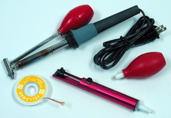
Image: Desoldering braid, pump, bulb, and iron
Which is best among desoldering braid, pumps, and irons depends on preferences. I personally like desoldering irons most, but I keep braid around in case some solder is particularly difficult. Pumps are fast, but do not always get all the solder. Braid takes a lot of time and can be messy and difficult, but tends to get the most solder in all uses. Irons are by far the easiest and are a bit more effective than pumps, but can also leave some solder behind.
For single components with many terminals, try to remove as much solder as possible. With most the solder removed, the component should be capable of removal with a light amount of wiggling. If only one terminal is being problematic, heat that terminal while pulling the component away. If a component is generally problematic because of lower quality desoldering tools, some pliers may be necessary to remove it, which may damage the PCB.
Electric Safety
Electricity can be extremely dangerous. But the great thing about PCBs is that they do not require much voltage to function, and they are not much of an electrical danger because of this.
Voltage only tends to become a danger around 30 or more volts. Most PCBs function at 5 volts, some at about 3, 8, or 10. The voltage in PCBs is not only low, but also about unnoticable to the touch. Game PCBs also generally do not use components that pose any dangerous (such as strong capacitors and inductors)
It is generally fine to handle a bare PCB while it is plugged in. I have personally handled about 50 unique live PCBs without any problems. But do not hold me responsible if you happen to find a way to shock yourself.
If you want to be extra certain that a PCB cannot harm you, there are a few precautions. Controllers should be tested to see if they are functioning in the first place (this is a good practice to make sure the PCB is sound anyways); if a controller is functioning properly, it should not have any flaw that presents a danger. Also you can wear gloves when you first plug in the extracted PCB and use a multimeter (voltmeter) to check the voltage coming from the cable and/or battery; touch the multimeter, on both AC and DC settings, between all the point where they meet the PCB; you should not get a reading of over 12 volts; unless there is a huge capacitor or inductor (which there should not be), the PCB cannot be dangerous when it is plugged in. You could also just work with gloves the whole time anyways, but gloves are not full protection either.
While controller PCBs are generally safe even when live, you should still practice a few precautions. Make sure you (especially your hands) and your workspace is dry; thick moisture can make a shock more likely, and can make damage occur more easily. The same can be said about metal and other conductors; work on an insulated area and do not wear jewelry.
And while controller PCBs are not dangerous, other electronic devices certainly can be. Do not make the same safety assumptions about other types of devices. The open and live insides of consoles and computers can be especially dangerous. Wall sockets are 100 to 250 volts, depending on where you live. Keep in mind your feet on the ground can function as a ground for a higher charge and voltage. Make sure you understand other types of devices before working them.
PCB Mapping and Soldering
The addition of soldered wires on an extracted PCB often looks crude to the uninitiated, but it is in many circumstances the best option for making a joystick controller function. Remember, the physical length and uniformity of electronic connections is pretty much irrelevent.
Before extracting a PCB, make sure all the functions are working properly so you know that the PCB is sound. Once a PCB has been extracted, if the cable is not secured strongly to the PCB with a harness, it is a good idea to reinforce the cable's connection with hot glue, or temporarily desolder it away (take a photo or write down where the different wires connect).
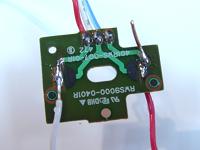
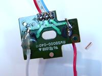
When wiring a PCB extracted from a pad controller, you need to solder a wire to the signal for each of the needed buttons, and one or more wires to each of the unique grounds used by those signals. The ground is usually shared around in the PCB and therefore can be shared among all the signals. If the ground is not completely universal, you will need to pair each unique ground with its corresponding signal. Even when the ground is universal, some builders prefer attaching a wire to each ground at each button.
There is usually a large area for each signal (and another with it for the ground) under each button on the PCB. You need to figure where to attach easily each corresponding wire on the PCB. You may find a diagram that lays out the various points of attachment here or elsewhere online. You can recognize grounds if their paths are used in more than one button.
The best way to map a PCB is to rest the PCB on something nonconductive, plug it in, get a wire, and tap the ends around on the paths of the PCB, noticing what commands occur, to figure what each path represents. Again, signals will usually have unique paths while grounds (commons) will get shared. Use this to recognize paths and nodes where wires can be attached. (This is the method I have used in mapping most my PCBs. A controller PCB should not have enough voltage to shock you. They are usually 5 volts, upwards of 10, and you should not even feel anything. I have not been shocked doing this, grabbing many plugged PCBs in many ways, but do not hold me responsible if you manage to find a way to hurt yourself doing this.)
In soldering a certain model of PCB for the first time, I recommend testing the PCB often. Every few attachments, check if things are working properly. Start by connecting a ground and test the signals as you go. This testing will help you narrow down when and where things go wrong in the soldering process.
Each chosen place to solder should not come in contact with other soldering points or components or nodes; this can cause signals to constantly be engaged, or other problems; masking like aluminum foil with a small hole can help in soldering only a small point. You will need a wire cutter and stripper to prepare the wire for soldering.
If necessary, use an abrasive tip like a wire end to scratch rubber or the light-green protection and expose metal where solder can be attached (a craft knife or rotary tool with a small abrasive tip is good for this too). It is even possible to solder wire to thin paths among other paths; use a pin and very carefully scratch the correct path and avoid scratching the others (it is not easy); support for the wire and immediate glue will likely be necessary to keep a solder like this attached and not tearing the path away.
There are a couple ways to attach wires to the PCB. You can attach the wire directly to metal plating on the surface (bending the wire end to an L-shape or placing the wire on its side can help in this). Or you can drill a hole using a strong 1/16" (2mm; I tend to recommend at most 1/32" or 1mm; small rotary tools are great for this too) or less drill bit by the metal plate and thread the wire through the bottom to solder it like standard soldering is done (this can be tricky and should not be done on double-sided PCBs).
Solder points using through holes can be replaced using different wire. Heat the wire end protruding from the solder point while pulling the wire out. Make sure to recreate the hole by pushing the tip of the iron into the hole or by using a desoldering tool, or just push the new wire through while the point is heated. Add some fresh solder or flux to remove oxidation.
Do not pull hard on cooled solder joints; the metal plating (especially in smaller areas) can easily be ripped from the PCB. Sometimes solder touching a wrong location can be cut away using an utility knife. If some of the trace is accidently removed, it can often be replaced by soldering wire to the ends of traces at the gap.
If an attachment does not seem to be holding (often because rubbery substances are melting in the way), scrape the metal surface again.
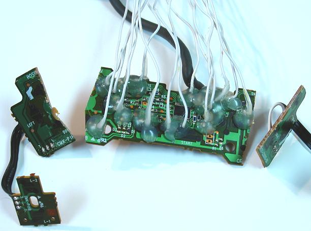
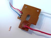
Image: Finished soldering: most solders were done on nodes reached from actual button spots, others were attached to detailed scratched paths; the plan was clustered so much of the PCB could be cut away using a hack saw; the solder points were glued because the 20 AWG wire used is heavy and rigid
Parts of the PCB that are not critical (like motors and often shoulder PCBs) can be desoldered or cut away from the rest to make it smaller using a strong tool. You may want to try to cluster the solders to make this work better. Just be sure not to cut something essential away; you will have to replace paths and/or components if it makes the PCB malfunction. A subsection below discusses this.
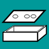
A box (called a project box/enclosure in electronics) or groove in or box built into the bottom of the control panel is often made to house and protect the extracted PCB.
Some controller builders also sell soldered (wired) extracted PCBs.
Solderless Extracted PCBs
A few specific models of controllers can be utilized without soldering; this method is often called the spiffyshoes hack after the nickname of the person who brought it attention.
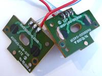
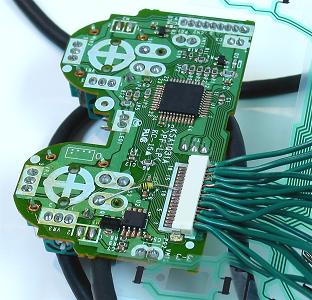
Images: PS2 controller without solderless structure; PS2 controller with possible solderless structure (note smaller font)
The following models of PCBs can use the solderless technique:
- PS1 Dual Shock A (Late Version)
- PS1 Dual Shock M
- PS2 Dual Shock A (Early Version w/ Resistor)
- PS2 Dual Shock A (Late Version)
- PS2 Dual Shock M
- PS3 Sixaxis
- PS3 Dual Shock (Early Version)
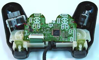
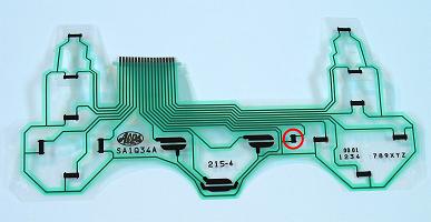
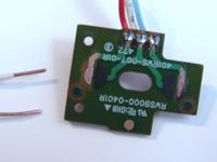
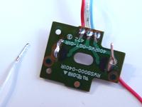
Images: Opened controller that can be used without soldering; The membrane face used by the controller, the extra button (which is actually a resistor) circled
Basically, all that is done in using one of these controllers is inserting stripped wire tips snugly into the terminal used by the membrane switches; this membrane has a path leading to the terminal for each function. You need 22 to 26 AWG solid (not stranded) insulated wire, and the tips stripped about 3/16" for PS1 and PS2 PCBs; 24 AWG solid with thin insulation (like extracted from shielded wire) stripped about 3/32" is necessary for PS3. The best wire for all solderless PCBs is extracted from 24AWG multiple solid cable. Since some wire can be a bit thick when lined together, you may need to strip every other wire end a bit extra, or part every other wire, to make them fit. You may want to keep the tip of the membrane inserted to make the fit more snug.
Images: Starting inserts; Inserts finished and working
You can cut the tip off the membrane when using a PS1 model, but you may need the membrane if you are using a PS2 or PS3 model. The PS2 model has two more paths than the PS1 model; one path is a ground specific to the start, select, and analog buttons; the other path is for a resistor; the PS3 has another resistor and two more paths. The PS2 or PS3 controller will engage most the buttons when it does not have the resistor(s) and ground in the membrane attached at the appropriate terminal slots; either the membrane or a 5K to 10K resistor (cannot use the membrane on the PS3 PCB when doing solderless) wrapped (staggered) around the bordering wires must be installed for the PCB to function properly. You may need to angle the membrane and wires so they make proper contact, so the added resistor will work much better.
Images: PS1 PCB with wire wrapped to hold it in place; PS2 PCB with hot glue added to hold wires in place
When finished inserting, find a way to secure the wires so they will not fall out. One way to do this is to use long wire (about 12" - 16") from the start, bunch the wires together, add some fastener to them, and loop them around the PCB. Another way is using hot glue; be sure that all the wires are working where they are placed before doing this more permanent securing. The glue is risky and I do not recommend it.
Images: PS3 PCB with thinly insulated 24 AWG solid wire and staggered 8.2K wrapped resistors
As simple as this may sound, it can be very frustrating; wires slip out and do not like to fit sometimes; getting to the point where every wire is inserted properly can take a long time. This process can be hit or miss; I much prefer soldering over doing this. The wire can also warp the terminals so the membrane no longer works well with the PCB. Solder makes things much more durable as well.
But now for a solderless hack, ShinJN and Toodles came up with a PCB and connectors that can make this much easier. The object into which the membrane is inserted is called an FFC (flat flexible/ribbon cable/jumper) or FPC (flexible printed circuit) connector. These FFC connectors and flat ribbon cables can be ordered from electronics stores. Playstation PCBs using these use right-angled, 1mm pitch FFC connectors; PS1 versions have 16 positions, PS2 versions have 18 positions, and PS3 versions have 20 positions.
PICTURE
The adaptors produced by ShinJN and Toodles have a flat ribbon cable inserted into the FFC connector on the Playstation controller PCB. The other end is inserted into a FFC connector installed in a custom PCB. The custom PCB has traces that lead to solder points where wires can be attached for commons and signals (terminal stripes can be installed), and traces where resistors can be installed. These adaptors were designed for early PS3 controllers, but using 16 and 18 position FFC connectors and cables, they can be modified for PS1 or PS2 PCBs.
Converters
The fact that most controllers standardly work only for a single system is one of the biggest reasons that joystick controllers are not very popular. Having a large, expensive device that can only work on one system tends to be unappealing. This is the greatness of converters; game controller converters make PCBs from one or more system work on one or more other system. Converters can add enormous versatility to a joystick controller.
Converters are made using the socket of a system(s) and the plug of another system(s). Between these are different electronic components that make the electric signals of a system(s) emulate the signals of another system(s). Converters generally only work in one direction; they cannot be used in the opposite direction of their design.
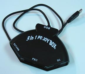
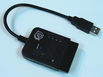
Images: Converters
The quality in the design of the components in a converter can determine whether the converter lags or not. Try to find recommended converters that do not lag.
The conversion of the signals from one system to another does not always have to be entirely accurate. Slight variations often work. This variation is not a problem until third-party PCBs get involved. First-party PCBs generally do not have problems with converters because the converters were designed specifically for them. But, because slight variations can work, third-party PCBs often have variations as well. When the variation of a third-party PCB meets the variation of a converter, problems can develop. This is one reason that first-party PCBs tend to be better. (It should be noted that Toodles tests and makes sure his PCBs function with many converters.)
Variations in signals also mean that stacking converters often does not work. As an example, a Playstation controller, plugged into a Playstation to Dreamcast converter, plugged into a Dreamcast to PC converter, will likely have problems.
The availability of converters has a huge impact on choosing the PCB used in a controller. If a converter can make a PCB work easily on another system, there tends not to be a need to use a PCB from the other system.
Because of converters, Playstation 1 and 2 PCBs are among the best for use in a joystick controller. There are many converters that make Playstation controllers work on other systems. Converters available can make Playstation PCBs function well on the Gamecube, Dreamcast, Saturn, Xbox, Playstation 3, and PC; the same versatility cannot really be said about the controllers made for those systems. Dual Shock controllers are preferred slightly because they have a little better compatibility with converters and games. Too bad there are not currently wireless converters though.
Note Xbox 360 and PS3 controller PCBs work on PCs (drivers are needed and should be installed before plugging it in; Xbox 360 only works with Windows).
PCB Diagrams
This subsection contains images with labels for many different PCBs.
The labeled points are only suggestions as PCBs can be exploited in many different ways as traces lead to many places. Signals are circled in blue. Main grounds are circled in red. There is generally only one ground possible in each PCB; some newer PCBs make the illusion of multiple grounds by creating required interactions between parts of the processor; when a ground is not the actual ground, it is labeled common, which is short for common line, ie they have a common connection. Commons function in the same way as grounds. Different commons are labeled in different colors. Some ground/commons may circle points that look empty; this suggests that the ground/common covers many areas and the spot can be scratched for an attachment point.
The voltage points are circled in yellow with a corresponding number. This is only important if you need an energy source for an analog joystick or LED, or maybe for multiple PCBs. Actual voltage often depends on the system or converter in which the controller is plugged.
Keep in mind that some controllers (like PS A controllers) may have the same model information and contain different PCBs.
If this subsection does not have your controller, refer to the PCB mapping subsection or try to find a diagram elsewhere. The PCBs in most these images are not augmented (they do not have added wires).
Wire
The best wire for controller electronics will usually come with the description "hook-up". It is insulated and comes either stranded or solid in various thicknesses.
Stranded wire is made up of multiple smaller threads of wire (similar to the fibers in string), while solid wire is one whole length of metal. Which to use is a matter of preference, but most prefer stranded wire. Stranded wire is much more flexible and prone to fraying, while solid wire retains its shape and does not fray. Flexibility will make the wire less hard on soldered joints and easier to twist, but will make it more difficult to organize. Fraying can make the wire more difficult to work and cause undesired contacts. Stranded wire also tends to hold better in crimping terminals, and has more surface area to bond with solder. Plus you can tin stranded wire with solder to make it solid.
Thicker wire will be less flexible and fray more, while thinner wire will be more flexible and fray less. Wire thickness is rated usually according to AWG (American Wire Gauge); the higher the number, the thinner the wire. Here are some measurements which exclude insulation (which can vary in thickness depending on how the manufacturer makes it; sometimes the thickness of the insulation will also be noted in wire products):
- 18 AWG - .0403" / 1.024mm
- 20 AWG - .0320" / 0.812mm
- 22 AWG - .0253" / 0.644mm
- 24 AWG - .0201" / 0.511mm
- 26 AWG - .0159" / 0.405mm
- 28 AWG - .0126" / 0.321mm
- 30 AWG - .0100" / 0.254mm
Standard Wire Gauge (SWG) uses a similar scale, but is about 20% thicker than AWG of the same number. This difference translates to about one number difference equal to the same thickness (like 20 AWG about equals 21 SWG, and 24 AWG about 25 SWG).
For PCBs and devices, 20-26 AWG (I have come to like solid 24 AWG most) insulated wire has an appropriate thickness, works well with crimping (especially for .110" connection and chaining), and fits into a PCB well. 18 AWG wire is too large and rigid, and 28 AWG is often too fragile. Color-coded connectors for 18-22 AWG wire will be red and not blue or yellow; 24 AWG wire and folded 26 AWG wire works for red connectors as well, but do have very small connectors coded yellow for them.
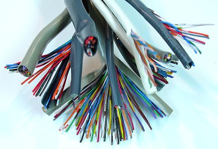
Image: Various outdoor wires containing 8 to 50 individual, insulated, unattached 24 AWG wires
Using different colors of insulated wire can make it easier to distinguish each wire in the mess that can likely develop. Thinly insulated wire in many colors can be extracted from certain multiconductor cables like shielded and outdoor wiring and phone cable (and it can be much less expensive too). Having just two colors, one for signals and one for grounds, can help a lot. If you are going for a certain inside look, the variety of colors may not matter to you. Modified computer cable (like ATA cable) can work too.
Labeling tape around wires like little flags can help when putting the wiring together; there are adhesive flag wire products that specifically do this (they are often called wire markers).
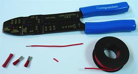
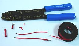
Terminals and Crimping
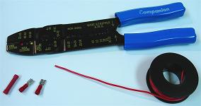
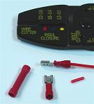
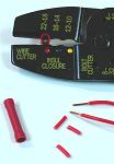
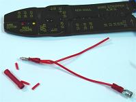
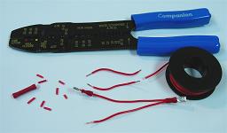
Various terminals and connectors can be placed on the ends of wires. Like solder, terminals attach wire to switch terminals on devices. They can also be used in certain terminal blocks. The only tool they often require is a crimper. Insulated terminals (which are usually color-coded) use oval-shaped areas on crimpers, while non-insulated terminals (which are usually bare) use U-shaped areas on crimpers; pliers can also often be used for crimping. Terminals come single-barrel or double-barrel; double-barrel terminals crimp in two locations and hold stronger. Insulation can also come separate and removable; these forms of insulation are heat-shrink tubing, sleeves, housings, and boots.
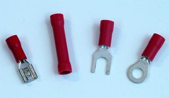
Image: Terminals and connectors (left to right): female quick disconnect, butt connector, spade (fork) terminal, ring terminal
Terminal crimping may be preferred over soldering because it is quick, easy, and clean. Soldering may be preferred because it requires no special pieces and is less bulky, and wire can slip out of crimped terminals.
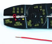
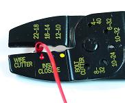
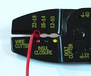
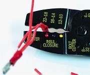
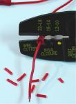
Crimping is a pretty easy process:
- Cut the wire(s) to the needed length with maybe a little slack.
- Strip the end of the wire(s) for the needed length of bare wire (about 1/4" or 1/3") using the corresponding size of stripper.
- Insert the connector in and level to the crimper in the corresponding size, then the stripped end(s) into the connector (the bare wire can be folded against the base of the wire first for a more snug fit).
- Crimp the bulk of the terminal using the crimper.
Standards microswitches fit .187� (3/16�) female quick disconnects (often abbreviated QD). This size is used on all Sanwa, Seimitsu, and Happ joysticks (without wire harnesses) and buttons with a standard microswitch attached. Some joysticks have .250" (1/4") terminals. Note also that quick disconnects have thickness ratings, usually about .02" or .032" (about .5mm or 1mm); get the smaller thickness or it will likely not hold the terminal.
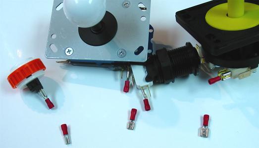
Image: .110" female quick disconnect on and by Sanwa button, .187" female quick disconnect on and by Seimitsu joystick and Happ button, .250" female quick disconnect on and by IL Eurojoystick
Most buttons not attached to standard microswitches use .110� female quick disconnects. These are mainly for Sanwa and Seimitsu buttons. Larger quick disconnects can fit on these terminals, but they are less secure. The problem with .110� quick disconnects is most hardware stores do not carry them (though some automotive stores have them), so you probably have to order them online. If you are making an order for Sanwa or Seimitsu buttons, check to see if they also sell these quick disconnects so you can save time and money getting them with your other parts.
Two connects are needed for each button, and eight are needed for each joystick that does not use a wire harness.
Terminals such as quick disconnects can also be soldered to wire; I tend to prefer soldering wire to terminals because it is about a 100% joint. Noninsulated, single-barrel terminals are usually best for simple soldering. But both soldering and crimping can be done. The wire can be tinned with a lot of solder, inserted, crimped, then heated so the solder bonds inside; this is a very strong joint. And, again, wire can also be directly soldered to terminals.
Quick disconnects can be difficult to remove from switch terminals; a flat screwdriver can help in removing them.
Twisting
The other option to device switch connections is simple wire twisting. It is not as strong as soldering or crimping. Twisting also requires a wire cutter and stripper (some pliers can substitute in these functions). It needs thin and well-stripped wire, with stranded (not solid) wire working much better. Wrap the wire end(s) through and around the hole in the switch terminal.
But twisting also has its use in conjunction with crimping and soldering.
Splicing and Chaining
Splicing involves connecting two or more wires together. The main use for this is spreading the ground around to different devices.
When more than one device uses a ground, it can be distributed by chaining it to all the devices that need it. Regardless of connection, the two wires being spliced can be twisted together before being connected. With a crimping terminal, both wires are inserted and crimped into the same terminal. With soldering, they are both soldered in the same spot. With twisting, they are just twisted together around the switch terminal.
Splicing can also be done using a terminal strip.
Note that chaining the ground (or common) does not put terminals at the end of the chain at a disadvantage because electricity travels so fast.
Joystick Connection
Most joysticks have each of their four switches open, each needing a ground and a signal. Since the base of the joystick moves opposite the top, the corresponding switch to each direction will be on the opposite side on the base. If the ground is universal, it can be chained to all four. If some have unique grounds (commons), corresponding commons need to be attached.
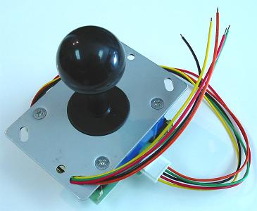
Image: Joystick with a wire harness
Other joysticks have a built-in PCB and a wire harness. These wires just need to be linked to a single ground and each corresponding signal. However, this is a problem if some directions have unique grounds (commons). When the wrong common makes contact with a direction, it can engage other commands, or make the PCB generally malfunction. Besides avoiding multiple-common PCBs, there are various ways to deal with a joystick in this situation:
One way is to see if the different commons just require different resistance. In this case resistors can just be added. This is rarely the case though, and probably not worth the effort of checking.
Another way established by Toodles is to use integrated circuits like 4066 and inverter chips to sort the commons. This can be complicated.
The most direct way to counter this problem is by partly bypassing the wire harness. You can cut contact between the joystick switches, the PCB, and/or the wire harness for different commons. You can do this by cutting contact between the switch ground terminals and the PCB, or by carving away small parts of the paths on the PCB, and connecting common wires directly to the ground terminals on the switches. For example, some X-Box 360 wired PCBs have three different commons on the directional pad, one for up and down, and the other two for left and right; ground circuits could be cut for left and right and each switch could get its common wire attached directly, and the wire harness could be used normally for the remaining connections.
The other way to fix this is to change the joystick into an open-terminal version. Standard microswitches from various manufacturers can replace the PCB version without changing the height of the joystick (even for the JLF); if the joystick uses levered switches, you may need the corrent model of microswitch. You can also just cut or desolder away the PCB and use the remaining switches with their bent terminals and attach wires using solder.
PCB Mounting and Insulation
PCBs should be mounted where they do not move around much and do not come in contact with conductive surfaces; when a PCB moves around freely, it can wear down connected wire joints and come in contact with other conductive surfaces (like open wires and terminals) and function improperly. And often it is a good idea to insulate open conductive surfaces so they do not oxidate as much and do not make improper contacts.
The usual way to mount a PCB is to screw (or bolt) down holes in the PCB. Very often extracted PCBs have holes that mount the PCB in the controller, and custom PCBs should be designed with mounting holes. If no holes are present in a PCB, they can be drilled; look for places in the PCB that do not have traces or components present; PCB material is very tough; it is often best to transition small to larger bits using strandard twist bits; make sure to prop the PCB against something so it does not bind and start spinning around on the drill bit. Screws are usually made of conductive material (metal); this is not a problem if the screws do not make contact with any conductive area besides maybe the PCB ground. Glue is another way to mount a PCB.
If the PCB is mounted against a conductive surface, it can make it not function properly as undesired connections are made. If you are not sure if a surface is conductive or not, take a signal wire and it ground wire and touch them very closely on the surface and see if the corresponding command engages; placing the nodes of a multimeter set on high resistance or diode testing close together on the surface is a better way to test conductivity. To counter a conductive surface, insulated spacers can be added to the screws that mount the PCB; plastic tubing from many places like pens and shrink tubing can also work for this function. Conductive surfaces can be insulated also by adding a finish like varnish or clear coat as most finishes have plastic, insulating attributes; it is often better to add some spacing though.
Project boxes are another option for mounting the PCB. Project boxes are boxes made of plastic (usually plastic, sometimes metal) that are designed to hold electronics; in a sense, most electronic products (including a joystick controller) are held in some kind of project box (often with buttons mounted in the box). The PCB goes in an insulated box and the box is mounted. Often it is not necessary to mount the PCB inside the box either. Project boxes can also be custom-made simply by putting together the sides using material like wood or acrylic.
While some conductive surfaces on the PCB may be open, it can be a good idea to insulate all other electronic surfaces to make the controller more durable less likely to have problems. Thick solder joints (like those used in wire connections) are not really vulnerable to oxidation, while much thinner PCB traces can be (this is why PCBs usually have layers of insulation). It is not really a significant issue to have open surfaces on thicker metal (like in terminals); some surfaces may oxidize a bit or have a very unlikely stray contact; insulating all surfaces is mainly about giving the highest quality to the electronics. Wire should have insulation (it will very likely malfunction if it does not). The other main open surfaces will be on quick disconnects and switch terminals; these can be covered using boots, heat-shrink tubing, sleeves, and special housing; certain arcade parts are designed specifically to cover the two terminals and connects at the base of buttons; some quick disconnects also come with insulation covering the entire terminal. If you want that extra quality, insulate everything, but it is not all that important.
Cable Modification and Connectors
Modifying cables may be much simpler than you think. The most common reason for modifying the cable is to add a connector that can make the cable detachable. Also, in the case of custom PCBs like those made by Toodles, different cables can be made so the same controller can change systems just by changing the connected cable. Plus, cables of better quality can be exchanged. Be sure not to lose track of where the different cable wires connect to the PCB.
A simple cord is made of two or more insulated wires, a connector, and a cover (like tubing). A connector is a detachable and interlocking component containing two or more terminals. Usually, one side of the connector has a male or female interlocking set of terminals (often called pins), and the other side has other terminals connected to the interlocking terminals where wires are either crimped or soldered to the connector. The most common connectors are wall power sockets (female) and electric plugs (male).
A cable is a cord used in electronics (not just simply for giving power). The most simple cable connectors are coaxial. The term coaxial describes things that a circularly symmetric (like a bullseye). Coaxial cable and connectors are made by layering alternating conductive and insulated layers, usually around a conductive core. Popular coaxial connectors are used in audio and video (RF, AV, and component) cable, headphone and music jacks, and power/barrel connectors/jacks (like for chargers and adaptors, which may be useful in building a rechargable controller).
All controller cables really do is directly connect terminals on PCBs, usually pins on the processor in a controller PCB, to the pins in a console or computer plug then socket, to processors in a computer or console. The main thing that is done in modifying a controller cable is making sure these direct connections remain the same. A cable can be cut at a desired location and have a pairing of male and female connectors with the necessary terminals connected complementary to the wires on each side of the cut (color-coding should make this easy).
There are many kinds of connectors. Some less feasible for controller cable work include rectangular connectors (these include wire harnesses and similar plastic grids of sockets and pins) and circular/minidin connectors (most commonly seen in mouse, keyboard, S-video and Xbox safety connectors; these are usually expensive). Connectors most appropriate include D-subminiature, modular, and USB connectors.
D-subminiature (D-sub) connectors have tightly fitting rims filled with pins arranged usually in staggered rows. D-sub connectors are most familiar in older PC connections (now commonly replaced by USB). They are abbreviated in the form DB-nn; standard ones usually have two rows of pins, while high density ones usually have three. The most common ones are DB-09, DB-15, DB-15 high density (like in VGA cable), DB-25, and DB-37. They have mounting brackets and easily assembled housings. Crimping versions of these use a special crimper, while solder version simply require solder. D-sub connectors are a bit bulky, but they are easy to use.
Modular connectors have a dense side-by-side arrangement of pins that often click and hold in a key-shaped socket. Modular connectors are most familiar in phone and ethernet connections. They are abbreviated in the form RJ-nn and nPnC; RJ-nn refers to specific models, while nPnC refers to characteristics (positions and contacts). The most common ones are 4P4C (includes RJ-09, RJ-10, and RJ-22), 6P6C (includes RJ-11, RJ-12, RJ-14, and RJ-25), 8P8C (includes RJ-45), and 10P10C (includes RJ-50). Special mounting or brackets soldered to shielded versions will be needed to install these in a controller. Crimping versions also use special crimpers (which involve inserting unstripped wire) and solder versions that are difficult because the wires are so densely arranged.
USB connectors have become the connectors used most in computer cables. They contain four or five terminals compactly arranged. More common versions include the four-terminal Type A (the original and most common version; the PS3 and Xbox 360 have sockets for them), the four-terminal Type B (a square version often used in custom PCB sockets), and the very compact five-terminal Micro-B (PS3 controllers use this as a socket). Special mounting or brackets soldered to shielded versions will also be needed to install these in a controller. Usually wires are soldered to USB connectors.
The connectors for controllers are often designed by the maker of the system to make it more exclusive (custom connectors are often called proprietary connectors). It is not so viable to build these cables, but full assemblies of them usually work well, especially first-party ones. You will likely need a multimeter to figure what pins in the plugs lead to which wires in the cables (touching a signal to a cable wire and its common to the pins in the plug can substitute in figuring this). It is good though to see newer systems using USB connectors.
Cables are covered by various kinds of insulated tubing made of plastic and/or rubber materials like PVC (which are also used in wire insulation). Cable used in manufacturing generally is produced complete with the differently colored wires (conductors) and tubing with a uniform inside and outside diameter. In custom work, tubing that can change diameter called heat-shrink tubing is often used; heat-shrink tubing is initially at a wider diameter, shrinking to a smaller diameter (usually about half the diameter) under the presence of heat (like from a hot air gun or blowdryer); the shrinking process cannot be reversed; heat-shrink tubing is rated for diameters before and after shrinking, along with thickness and color.
The various connectors have different forms of housing and hoods that enclose and protect the area where the wires in a cable meet the connector. Housings and hoods have many other names including fittings, surroundings, boots, and covers. Different connectors have different housing assemblies often using a pinch to hold the cable in place so wires are not pulled from the base of the connector. Other connectors like modular and USB often have hoods that fit tightly on the cable and slide over the connector (glue like rubber cement is often put on the end of the tubing before sliding the hood over); hoods often have spaced grooves that function like a spring for stress relief. As a substitute for hoods, heat-shrink tubing is often used. It is important to attach housings and hoods in a way that keeps the wires from being pulled from the connector.
Cables also use various forms of shielding (screening) to protect against electronic noise. Some cable is produced with foil lining beneath the tubing and surrounding the wires. Many cable assemblies come with a ferrite bead (core/ring/filter) that protects the cable near the computer where it connects (computers produce a lot of noise); these can be purchased and added easily (they come in locking halves).
Another protection against noise is an extra shielding ground wire in the cable. The extra ground often attaches to the same pin in the controller plug, but is connected to a different solder point on the PCB that does not lead to anything; it is important that the shielding ground wire is not connected to the other ground wire aside from the plug pin; do not use the ground wire that does not connect to traces for signal or other grounding as this will remove the shielding. Sometimes the shielding ground wire is thicker than the other wires (this is the case in many Xbox controller cables).
Because of timing critical to nanoseconds, the length of cables can have a negative impact on the performance of the PCB. USB cables are advised not to exceed 5 meters (about 15 feet). For game controllers, I would suggest not exceeding the length of cable used by first-party controllers for their systems. Thicker wire in cables can help longer cables perform better.
Terminal Strips and Organization
Terminal strips are connectors containing a series of clamping or fitting terminals each usually leading to connected solder points or another terminal. They are commonly used in organizing and distributing wire. They make it so lengths of wires attached to a controller PCB can be uniform and non-specific, the signal and common wires can be much more organized, and the functions of a controller can be modified more easily. The strip can also be used for duplicating or converging signals and commons (splicing; multiple wires can use the same terminal); this is useful in making different switches do the same thing, or making a controller use more than one PCB.
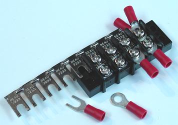
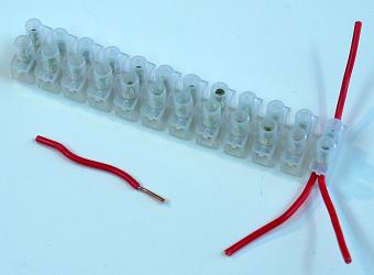
Images: Barrier strip with a jumper strip (which can be trimmed) connecting three sets, and some terminals; European-style terminal strip with some stripped wire tips secured
Spade and ring terminals fit wire ends into American-style terminal strips (also called barrier blocks). Spade terminals can slide under screws for easy movement, but are held with just friction. Ring terminals have to be installed and removed with the entire screw, but hold very strongly.
European-style terminal strips only require wire ends stripped about 1/8" to 1/3" (3mm to 8mm) to be secured. The ends get wedged down by screws. I tend to prefer European-style strips because they are easier and do not require connectors. And European-style strips can be trimmed down (divided) using a saw. European terminal strips have versions that can be mounted in PCBs (custom PCBs often use them).
Terminal strips have a pitch measurement that notes the distance between the centers of each terminal; smaller terminal strips have a smaller pitch measurement. Pitch is important for terminal strips that are mounted to PCBs.
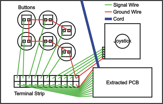
Image: Bottom view example setup for an extracted PCB
In putting the electronics together, with the commons (ground) and various signal wires attached to the PCB, link them to the proper button and joystick switches. Each switch needs the desired signal and its common. Use some splicing and chaining to distribute the commons.
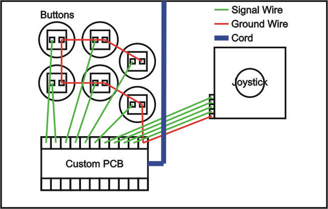
Image: Bottom view example setup for a custom PCB
There accessories can help in organizing wires. Wire mounts come in two main types. Looping wire mounts have hoops that are screwed down. Other wire mounts are adhesive and designed to hold cable (wire) ties. Cables ties are textured strips with a clicking slot that secures the strip smaller and smaller (they cannot be reversed). More and more popular than cable ties in wire organization is heat-shrink tubing; tubing can turn a group of wires into a more organized partial cable assembly; spiral wrap can work in a similar way. Planning of how the electronics in a controller are organized should be done ahead of cutting various wires so they are not too short or long (a bit of slack that can be trimmed is a good idea).
With the wiring set, thread the cable out, or position the remote at, a groove (like a keyhole) or hole in the front of the controller box (Bluetooth, like in official wireless PS3 and Xbox 360 PCBs, does not need this); a solid hole will require the cord to be desoldered and resoldered. Perhaps tie the cable in a knot or attach some kind of bulk at the area just before the cable exits the box to prevent potential yanking from damaging the insides of the controller. Different special grommets and bushings are designed for this (these are often used where cables exit gamepads); a simple grommet or ring could also be glued to the cable. Or instead of this cut the cable about where it meets the side of the box and install a D-sub, modular, or USB set of connectors to make the cable more independent of the controller.
It should also be noted that some controllers are made with all the buttons, joystick, and other devices wired directly to a D-sub connector. The connector is then attached to an outside project box with the other side of the connector connected to the various points on an enclosed PCB. This makes a controller PCB-independent, but also makes it more bulky. I tend to recommend fitting multiple and/or versatile PCBs (like PS1 or PS2 or Cthulhu along with converters) instead of using outside project boxes.
Multiple PCBs
Multiple PCBs can be used in the same controller, but troubles can occur in making them function together. There are a couple ways to do it. One involves project boxes with D-sub connectors that sit outside the controller, and the other involves splicing multiple PCBs within the controller to complementary signals and commons (grounds).
A D-sub is basically a plug that continues different wires. When using a D-sub with a PCB in a lone project box, the insides of the controller are sorted to the D-sub connector so that no PCB sits inside the controller and it is PCB independent. Outside the controller, each of these wires lead to the other side of the D-sub, which leads to wires connected to the desired locations on the PCB. Basically, an external project box is the same as a PCB inside the controller, but the different wires go through a connector which leads to the PCB outside the box. Different project boxes can then be made to use different PCBs for the same controller.
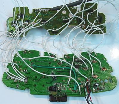
Image: PS1 DS H (early version) linked to Xbox 360 Madcatz 4716 (late version) by branching Xbox 360 main signals and grounds to the PS1 test points of similar locations, the Xbox 360 5V to the PS1 3.3V, and setting device switch wires on the PS1 button locations (the PCBs can be folded together so they are more compact)
The other multiple PCB method is housing multiple PCBs inside a single controller. Complementary signals and commons (grounds) for each PCB are in some way or another sorted to the same terminals on each joystick and button switch. They can converge at different points. They could meet on the switch terminals, but I do not recommend this. A good way is to link one PCB directly to another PCB in the complementary locations. Another good way is to have them converge in the same terminal strip. They will then have the same circuits completing on each PCB. Be careful that the commons and signals are sorted properly to avoid engaged switches.
PCBs linked to each other need to have their ground and voltage connected. It is necessary because a PCB, or more specifically an integrated circuit, needs to have power connections to function properly. If a linked PCB does not have power for the integrated circuit, it will cross signals and cause the other PCB to make strange connections.
But, as with joysticks using wire harnesses, the biggest problem for multiple PCBs has to do with multiple commons in individual PCBs. Again, if the wrong common makes contact with a signal, adverse commands often occur.
Having multiple commons is not so much a problem for project boxes; they can be sorted decently with some planning. But for multiple internal PCBs, this can make the PCB with the multiple commons malfunction. Imagine one PCB uses a single common ground while the other has two commons; the ground and one of the multiple commons are sorted to their various switches, which is not yet a problem; but then the ground is sorted with the second common to the other switches; because all the wires from the common ground PCB are linked (either with one another or through the PCB structure), and because the first common on the two-common PCB touches the ground, the first common will get linked to the second common causing the commons to combine and create problems.
Generally, it is recommended that PCBs using a single common are used when configuring multiple PCBs. Currently the most popular of these configurations is a PS1 PCB mixed with a Mad Catz Xbox 360 (late version) PCB because each PCB has a single common. This problem can be countered using transistors or integrated circuits that sort and separate the commons, but will take some effort. Keep in mind that there are converters and other versatile PCBs available too.
Electronic Components
The rest of this section involves electronic components and more advanced electronic work. This information is not required in making a controller, but it may be necessary in adding certain custom features. Below is a very summarized (though still pretty long) description of various electronic components and how they can be used in enhancing the electronics in a controller. It is very possible just to reference the various diagrams in adding the features; understanding components will help in troubleshooting and designing other custom features not mentioned in the rest of this section.
To understand electronic components, it helps to picture them as the parts in a machine driven by water, but the water always moves at the same speed (because electricity can be pictured that way for most purposes). Voltage can be viewed as the pressure (density) of the water (the amount of electricity that is trying to move at once), while current is how much (quantity) of the water is moving (the amount of electricity that is actually moving). The water comes into the machine from an outside stream (like a cord) or large tank (like a battery) and out a drain (the other voltage line, ie ground). If the water does not have pressure, an entrance, an exit, and movement, it does not do anything. Switches are like large levered valves, letting water flow or not flow.
Resistors distribute the water and can be viewed as smaller openings or filtered valves; they let different segments of the machine use smaller amounts of water and prevent it all from quickly going down a single path. Diodes are one-way valves letting the water only flow in one direction. Transistors are pairings of one-way valves (diodes) facing each other with a middle valve that enters between them; they only let water flow in the one-way valves if water flows or does not flow in the middle area, opening or closing the valves. The majority of an integrated circuit is a large, complex network of resistors, diodes, and transistors with a specific goal.
Capacitors are like small pressure tanks; they can take in small amounts of water and build it up to different amounts of pressure and release it at different times; the different times make pressure waves, or smooth the pressure, at different points in the flow, and can make delayed actions; they can also be used to create timed events in the machine. Inductors are like capacitors, but they center on holding a quantity (instead of pressure) of water with a similar pressure to the line like open adjacent tanks; they can affect how much water flows at different times. A resonator (oscillator) is like a sprinkler designed to sputter water out quickly to produce specific patterns.
Voltage, Current, and Resistance
Voltage describes the relative density of electrons between two separate objects. When the objects are linked in some way, the electrons moves from one to the other, producing current. Current describes the quantity of electrons moving between the objects during a given amount of time. The greater the voltage between two objects, the more potential there is for electrons to move with more force, producing greater current. In electronics, components are placed between the two voltages so work can be done on them. Many components produce a resistance as the electrons push through them as work is done, and even the best conductors have some small amount of resistance.
The most essential equation in electricity is Ohm's Law, which states: V = IR
In other words, voltage (V) equals current (I) multiplied by resistance (R). In other other words, voltage is directly related to the current and resistance in a circuit, while current and resistance are inversely related. Through the same component (resistance) in the same circuit, increased voltage will produce an equivalent increase in current, and decreased voltage will produce an equivalent decrease in current. Through the same circuit with the same voltage, if the component increases resistance, the current will decrease inversely, and if the component decreases resistance, the current will increase inversely.
Theoretically, if the two voltage sources are connected directly, and there is no resistance, the voltage will drop to zero, and the current will be infinite, basically instantly equalizing both sources. In reality though, there is at least some resistance in pretty much all objects, so voltage goes much lower and current much higher. This demonstrates that the direct connection of voltage sources produces problems like wasted energy (and the creation of a lot of heat), and that resistance is very important in making circuits. The separate charges in the cable and/or battery need to have some sort of resistance between them at all times.
Multiple components can be arranged in series, parallel, or a combination of both. A series connection is longer, with the outputs of components connected to the inputs of other components. A parallel connection is wider, with the outputs of components connected to the outputs of other components, and inputs connected to inputs. Series connections form a chain, while parallel connections are side-by-side. These different connections affect voltage, current, and resistance in different ways.
Parallel connections affect current and resistance, but not voltage. Since electrons are divided down more than one line, a different quantity of electrons will move through each line, and quantity describes current; the pressure in each line will remain the same, and pressure describes voltage. If the resistance in each parallel line is the same, the current will be divided equally, dividing by two for two lines, three for three lines, and so on. If the resistance in each parallel line is different, it will be divived in inverse proportions; if one line has twice the resistance of the other, it will run half the current of the other. The added current through all lines equals the current through their base (and output) line.
Because there is more openings through which electrons can move, parallel connections also lower the total resistance. If the resistance in each parallel line is the same, the combined resistance equals that resistance divided by the number of lines; two lines of equal resistance produce half the resistance, three produce a third. If the resistance in parallel lines is different, the total equals the inverse of the total of the inverses as shown by the equation: 1/RT = 1/R1 + ... 1/Rn; so if one lines has twice the resistance of another parallel line, their total resistance will be 1/RT = 1/R1 + 1/R2, or 1/RT = 1/1 + 1/2, or 1/RT = 1.5, or RT = 2/3, meaning the total resistance will be two-thirds the resistance of the line with lower resistance; this makes sense because the stronger resistance line gives 50% more of the weaker line's opening for electrons to move. Parallel resistance will always produce lower total resistance.
The total resistance through lines connected in series is easy to figure; they are simply added together. Two equal resistance lines connected in series produce twice the resistance; three produce triple. Two different resistance lines connected in series, one with twice the resistance of the other, combine to produce triple the resistance of the weaker line.
Series connections affect voltage and resistance, but not current. Since electrons go through the same line, the quantity down these lines will be equal, meaning the current will be the same; but between the series lines with resistance, pressure is going to be different as it transistions from an area of higher pressure, to a middle area, to an area of lower pressure, meaning voltage will be different between lines with resistance connected in series. If the resistance in each series line is the same, the voltage will divide equally; if two equal resistance lines are in series between the higher and lower voltage, the voltage between the two lines equals the average of the two voltages; if three equal resistance lines are in series, one middle area will have 1/3 the voltage, while the other will have 2/3 the voltage.
Multiple resistance lines connected in series form different voltages in what is called a voltage divider. Voltage dividers are important to analog signals like those used by analog sticks and triggers because they create incremental voltages. If series lines have different resistance, the voltage will be inversely divided. Divided voltage is calculated in the equation: VD = VT * RL / RT; the divided voltage equals the total voltage of the circuit, multipled by the resistance between the lower voltage and the division, divided by the total resistance of the circuit. If different resistance lines are connected in series, and the resistance line close to the lower voltage has twice the resistance, VD = VT * 2 / (2 + 1), or VD = VT * 2/3, meaning the divided voltage will be two-thirds the total voltage, or in other words the divider will have two-thirds the higher voltage, and one-third the lower voltage; if the resistance lines were switched, VD = VT * 1 / (1 + 2), or VD = VT * 1/3, meaning one-third the total voltage, or in other words one-third the higher voltage and two-thirds the lower voltage. Again, it is divided inversely proportioned to the resistances.
Total current in a circuit is equal to the total of each line's current. Total current in parallel lines is easy to figure; it is equal to the current of each line added together. For current in series lines, the total resistance can be added and divided into the voltage, or the voltage on the sides of one resistance can be calculated and used to determine current through that resistance (which will be the same current through the rest of the series line).
Analog and Digital Signals
Signals can be analog or digital. Analog signals represent varying degrees of a signal through modification of the electricity in things like its voltage, current, and frequency. Digital signals represent one of two states like a switch being on or off; multiple digital states can produce more detailed information. Though digital signals tend to represent newer technology following analog, controller PCBs started digital, but took on analog attributes later for the function of analog sticks and triggers (though these analog functions are often converted to complex digital signals).
A simple digital signal is either on or off. All electronic signals have analog attributes; they are made digital through the use of thresholds. Most often digital signals are seen as on or off when they go above or below a specific voltage determined by the interpretting component or device. An example can be a 5V transistor turning on when the input goes above 2.5V and off when the input goes below 2.5V (it is not generally this exact). Other digital switches can be based in other attributes of electricity.
Digital signals can be described using many pairs of data describing on and off. In terms of voltage, they can be described as higher voltage or lower voltage, or high or low, or H or L (this is commonly used to describe inputs and outputs on integrated circuits). Other descriptions include 1 or 0 (a bit), positive (+) or negative (-), yes or no, source or sink, and true or false (a boolean).
The oldest controllers (and Neo Geo controllers) were digital and did not even use PCBs. Each signal had its own wire going from the button through the cable to the system or computer; one other wire was the ground. Functioning digitally, each signal was normal high (off) and went to low when the signal made contact with the ground in each button's switch.
As more buttons were added to controllers, it was not viable to make thick cables with wires for each button. PCBs with encoding integrated circuits (processors) came into the picture so that signal data could be sent down only one or two wires. The encoder has an input for each signal; the output of the encoder changes based on each input being either high or low; the output compacts multiple signals into one line using high-frequency timing and transmitting a compressed data stream or specialized analog signal. The system or console has a complementary decoder that changes the encoded data back to individual signals.
For more modern controllers, makers wanted more precise controls for certain games, using signals with varying degrees of engagement, ie analog controls. To do this pretty much all PCBs incorporated gradually increasing and decreasing voltage for signals, using variable voltage dividers called potentiometers. Much more detailed encoders are needed to go along with this. Many PCBs transform the analog signals to digital using a set of digital signals (like 011001). In modern controller PCBs most the signals have analog attributes (often transformed to digital) excluding the option buttons (this is so designers can add analog functionality to any action button they choose). If a controller has analog sticks, it is analog; if a controller does not and is older (like in early Playstation and Saturn times and before) it is digital; otherwise it can be either.
Multimeter
A multimeter is a combination of a voltmeter, ohmeter, and/or ammeter (usually all three). A voltmeter measures voltage (both AC and DC). An ohmeter measure resistance. An ammeter measures current. These meters either have a digital or analog readout. I recommend the digital kind because it is much easier and more durable.
Each meter has a dial set to measure a certain range of an attribute. The number on a dial setting is the maximum that setting can measure; below this the setting will measure within about three significant digits, rounded at the last digit; for instance, the 20K ohms setting will measure up to 20000 ohms and will round to within 100 ohms. If the measurement goes well above the range, it will display an error sign like a * or 1; if the measurement is well below the range, or one of the wires is not connected, it will display three digits of zero or the error (depending on the meter and setting); meters can often sustain damage with prolonged connection to an error display. Try to estimate an adequate range.
Different models of meters have different attributes. Some can be more sensative or fragile than others. Some have multiple plugs where different attributes should be measured. Make sure to read the manual that comes with a meter to know and understand the way it functions and its limitations.
Voltage is measured when power (voltage) is connected (the circuit is on/live). Adjust the meter dial to read the proper range of voltage (for a PCB this will be DC usually 20V). The red line from the meter connects to the higher voltage and the black line connects to the lower voltage (ground). If the voltage reads negative, the black line is connected to the higher voltage. To measure the voltage level of various areas, connect the black line to the ground, and tap the red line to the various test areas.
Resistance is measured when voltage is not connected (the circuit is off). Measuring resistance on a live circuit will usually damage the meter, and it will not usually display accurately. Measure resistance by putting the red line at one end of a component or set of components, and the black line at the other; it does not matter which color line is on which side.
Current is measured when voltage is available, but one part of the circuit is cut (the circuit would be on/live if there was not the one break). The meter is used to complete the circuit, then measure how much current is moving through it. Place the red line on the higher voltage part of the broken circuit, and the black line on the lower. If the current reads negative, the black line is connected to the higher voltage. Current measuring devices are the most fragile. Make sure there is some resistance somewhere in the circuit when measuring current, because otherwise the current will be extremely high and damage the meter (often meters have a replacable fuse for this); do not connect the meter to completed live circuits because this will do about the same thing; connecting the lines of a meter to the voltage and ground of a PCB is an easy way to damage the meter. Measuring a PCB's current involves disconnecting either the live voltage or ground wire (either will get the same reading) for the PCB and completing the connection with the meter; measuring current to individual components involves disconnecting an end of the component and completing the line to it with the meter.
Multimeters also usually have a diode testing setting. If the red line is connected to the positive end, and the black line to the negative end, of a diode, it will show current flowing (usually a low resistance display). The diode setting can also be used to test if different spots are connected, ie test connectivity.
Capacitance is measured when voltage is not connected using a meter called a capacitance meter or some varieties of voltmeters. Capacitance meters are more specialized and expensive than the meters involved in a multimeter. Voltmeters (and some multimeters) with special functions for capacitance involve the timing of a charge or discharge involving a known current.
Switches
A contact switch has terminals connected to conductive contacts that become connected or disconnected based on different positions; the contacts open (disconnect) and close (connect) circuits. Joysticks and buttons are embellished versions of contact switches.
Contact switches have a number of poles and throws, which determines the number of terminals (leads). A pole (abbreviated P) is a unique set of connecting and disconnecting contacts; a pole can be regarded as a single terminal that connects to various other terminals in various positions, ie a main terminal; the number of poles is like describing the number of switches shared by the single component. A throw (abbreviated T) is a position of a switch that connects contacts. Throws function to make a circuit on (ON, closed, and connected), but switches can have other positions where all circuits are off (OFF, opened, and disconnected); the on function can be momentary (MOM) if the switch is biased and moves out of the position when it is not held; biased switches can be described as normally open (NO) or normally closed (NC); functions that are momentary or not biased can be surrounded in parentheses, like (ON) or (OFF), to show the switch does not normally hold the function. The number of terminals (leads) for a contact switch is equal to the number of poles times the number of connecting throws, plus the number of poles (PT + P).
Switches are described using abbreviations nPnT, which represent the number of poles and throws, and sometimes the set of functions the switch holds in each position. 1 can be represented as single, or S. 2 can be represented a double, or D. So a SPST (1P1T) switch is a single pole, single throw switch with two terminals that connects the poles (terminals) in one position and disconnects them in the other (this is the simplest switch). A DPST (2P1T) switch is a double pole, single throw switch with four terminals that connect each pair of throws in one position and disconnects them in the other; it is like two SPST switches share the same positioning.
A SPDT (1P2T) ON-ON switch is a single pole, double throw switch with three terminals that connects one main terminal to one terminal in one position, and that main terminal to the other terminal in the other; a SPDT ON-OFF-ON switch has an added position in which none of the poles are connected (this is sometimes described as SPCO). A DPDT (2P2T) ON-ON switch is a double pole, double throw switch with six terminals that separately connects two main terminals individually with two other terminals, and those mains to two other terminals in the other; it is like two SPDT switches using the same positioning; a DPDT ON-OFF-ON switch has an added position in which none of the poles are connected (this is sometimes described as DPCO).
Switches with poles and/or throws greater than two are described using numbers and can be assessed using the same logic. A 3PST (3P1T) has three poles, one throw, and six terminals, with three pairs of terminals connecting in one position, and disconnecting in the other. A SP3T (1P3T) ON-ON-ON has one pole, three throws, and four terminals, with one main terminal connecting to three different terminals in three different positions; a SP3T ON-ON-ON-OFF switch has an added position where no connections are made. A 3P3T ON-ON-ON has three poles, three throws, and twelve terminals, and basically functions like three SP3T ON-ON-ON switches using the same positions; 3P3T ON-ON-ON-OFF adds an all off position. A SP6T (1P6T) ON-ON-ON-ON-ON-ON switch has one main terminal that connects to one of six other terminals in each position.
Note that switches with an excess of poles or throws can take the function of a switch with fewer poles or throws. A SPDT can function as a SPST when one of the terminals is disregarded. A DPST can function as a SPST when two of the terminals are disregarded. A DPDT can function as a SPST when four terminals are disregarded, or a SPDT when three are disregarded, or a DPST when two are disregarded.
An intermediate switch is a special switch that inverts the contacts of multiple poles. A switch with two poles and two throws can have two main terminals and just four total terminals; in one position each main terminal is connected to a different other terminal, and in another position the main terminals exchange the terminals to which they are connected. Intermediate switches are unfortunately not commonly made; they are usually formed using a standard DPDT switch with a pair of wires cross-connecting the non-main terminals.
When momentary action is added to switches, the added set of functions are described differently. A SPST MOM-OFF ((ON)-OFF) switch has two terminals that are connected when the switch is held and automatically disconnected when released (it can be described as SPST-NO); this type of switch is used by most Japanese and control pad buttons. A SPDT ON-MOM (ON-(ON)) switch has one main terminal that connects to one terminal normally, and the other when the switch is held; this type of switch is used by most the microswitches in joysticks.
Switches that are not momentary can be described as latching. A latch has multiple stable positions. Microswitches can be argued as both momentary and latching because the deflecting plates create a medium resistance that makes them a bit more stable when they are engaged, giving them a unique feel when they are pressed. A toggle latch has multiple stable positions that can be set using the same action (retractable ballpoint pens have an example of a toggle switch).
Switches are installed in various ways including screw-in, snap-in, and soldering. Many switches come with added leads that are used only to solder the switch in place.
Switches with various functions are built into various devices that fill those functions. Some of these structures are described below:
Pushbutton - Pushbuttons are very simple momentary contact switches using a spring mechanism to connect and disconnect the contacts; some push buttons have a latching toggle action.
Tactile (Tact) - Tactile switches are compact versions of pushbuttons; standard tactile switches are often used in trigger and option buttons in control pads; soft rubber versions are used elsewhere in control pads.
Microswitch - Microswitches have deflecting plates for contacts requiring a small force to engage; they have a small button that is often enhanced with a lever which sometimes has a roller.
Toggle (Lever) - Toggle switches have a prominent lever they tilts solidly from one position to another; personally, I think they should be called lever switches instead of toggle switches because the term toggle has a special meaning in electronics.
Rocker (Seesaw) - A rocker switch is similar to a lever switch, but has an arc face, where one side of the face being pressed inward forces the other side of the face outward; I think they should be called seesaw switches.
Slide - Slide switches are like lever switches, but much more compact, and much more common in simple electronic devices; slide switches have a prominent node (often with grooves) that slides horizontally (does not tilt) to various positions; they also have the advantage of being less prone to accidental adjustment.
DIP Switch - A DIP switch uses the DIP structure with small slide switches; these are used for a large number of very compact switches for many functions.
Rotary - A rotary switch has a prominent cylinder that is turned into different stable positions (these often click).
Key - A key switch is a secure rotary switch requiring a complementary key to engage.
Analog switches, namely variable resistors and potentiometers, are used in analog functions. Special switches that can be controlled using electricity are created using transistors (which are put into integrated circuits) or relays; since most arcade buttons have simple SPST or SPDT switches, electronic switches are necessary for making them perform multiple actions.
Switches often have flaws that occur as the contacts connect and disconnect. Contact bounce occurs as contacts connect; during very small fractions of time, the contacts often bounce around, connecting and disconnecting very fast; this is usually only a problem for toggle functions. Also, as charges connect and disconnect, they can wear down the contacts. These problems can be helped using capacitors (often along with resistors) to stabilize these transistions (most PCBs have capacitors that handle stablizing).
Resistors
Resistors are the unsung heroes in electronics. About every even slightly complex circuit involves them. Resistors are used purely to add resistance in different areas of circuits as described by the equation: V = IR. They both divide and distribute both current and voltage.
Resistors limit the quantity of electrons that can flow through a circuit over time, ie resistors lower current. The limitation on current also separates the influence on voltage so it can stay higher in one place than another. Placing a limitation on the current distributed to various smaller circuits is critical in making a single source of current and voltage perform multiple tasks; when one part of a circuit uses a small portion of the current, its influence on the rest of the circuit is very limited. Without resistors, current would tend to flow down single lines instead of multiple lines. It is also difficult to manipulate the path down which electrons choose to flow without resistors. Plus simple functions would consume a lot more electrons (burn and waste electricity) without resistors limiting their flow. The field of electronics would not exist without resistors.
When resistors are placed in series with other components, they limited the current through those components. They can be placed before or after components, limiting current in the same way as long as they are in series. This is important for sensative components like LEDs and transistors.
In a simple circuit with one resistor and a higher and lower voltage on each end, voltage is divided simply with higher voltage on one side of the resistor, and lower on the other. When multiple resistors are connected in series, they divide the voltage between them, putting it somewhere between the voltage levels on each side based on the proportion and placement of the resistors. Resistors do not produce a moderate voltage outside of this voltage divider positioning. Voltage division is important in analog signals like those used by analog sticks and triggers.
In parallel circuits, resistors distribute current to various areas. This is the essential way to make multiple components function from the same voltage source, basically rationing current. The voltage stays the same down parallel lines.
Resistors help distribute the same voltage to various areas. If they did not limit the distribution, the two voltage sources would come in direct contact, and voltage would not exist (with enormous current), making other circuits basically turn off. If the voltage and ground in a PCB are connected, no voltage exists, and the PCB turns off (wasting a lot of electricity and producing a lot of heat, and possibly damaging something). Components like transistors and integrated circuits (processors) use voltage in various input terminals (pins/legs) to turn on and off. Voltage is distributed to the branches through resistors so that electricity is not wasted, and voltage in the entire circuit does not get dropped to zero when a switch is engaged or disengaged. Voltage distributed like this goes through what are described as pull-down resistors and pull-up resistors; pull-down resistors give areas lower voltage (made by putting a resistor between the ground and the area), and pull-up resistors give areas higher voltage (made by putting a resistor between the voltage source and the area); these resistors are not special components, just described this way based on how they are configured.
Resistance comes from giving electrons a limited opening through which to move. Resistors can be made from thin conductors (in wire and traces), but this is too fragile (especially because of the heat this generates). Resistors are usually made by mixing a certain amount of a conductor with an insulator, giving the same limited opening and a lot more durability.
Resistors are made of various materials, the most popular being carbon (either solid or film) and metal (film). Cylindrical ones are coded usually with four colored bands. The number of ohms of resistance is colored in the first three bands as figured by (1)(2) x 10^(3). The colors for ohms are (0 - black), (1 - brown), (2 - red), (3 - orange), (4 - yellow), (5 - green), (6 - blue), (7 - violet), (8 - grey), and (9 - white), like a rainbow. The first two bands form a two-digit number. Black (0) is usually only used for the first band if a single digit ohm rating is used, so the third band will also be black. The third band represents how many zero's are added on the end of that two-digit number. So black-brown-black is 1 ohm, red-red-brown is 220 ohms, brown-black-red is 1000 ohms, yellow-violet-red is 4700 ohms, brown-black-orange is 10000 ohms, and brown-black-yellow is 100000 ohms. Resistances of 1000 ohms are abreviated using a K that represents 1000 (like 100000 ohms is written 100K). The fourth band (which usually has a slightly bigger space between it and the other three) represents tolerance, which rates how exact the resistance is made; since resistance does not often have to be exact and inexpensive resistors function well in most circuits, gold (5%), silver (10%), or none (20%) will usually be seen.
Resistors also have a power ratings done in watts, commonly 1/8, 1/6, 1/4, 1/2, or 1 watt. This is not marked, but will show in the thickness of the resistor. Power in electricity is figured using: P = I^2 * R = V^2 / R. Power rating rates the maximum power that a resistor can take. If power going through a resistor is higher than it is rated, the resistor will burn and fail; if it is lower than rated, it will function properly, no matter how much lower. Many PCBs function at 5 volts; say 100 ohms is added to 5 volts, it produces 5^2 / 100, or 25/100, or 1/4 watt rating is necessary; but keep in mind the tolerance on resistors; if the tolerance is 5% (gold), the resistance could be as low as 95 ohms, meaning power could be 25/95, or over 1/4 watt, so rounding up to a 1/2 watt rating should be done in this case.
Because fewer electrons flow through at once, the more resistance in a resistor, the less critical the power rating. 1/8 watt resistors are fine for most signal applications; 1/4 or 1/2 may be needed for components like LEDs or power distribution. Here are some minimum power ratings for various resistances using 5 volts and 5% tolerance:
- 210+ ohm resistance - 1/8+ watts power rating
- 158+ ohm resistance - 1/6+ watts power rating
- 105+ ohm resistance - 1/4+ watts power rating
- 53+ ohm resistance - 1/2+ watts power rating
- 27+ ohm resistance - 1+ watts power rating
Too low of a power rating can create a lot of heat. Ironically, touching a low voltage is usually harmless, but putting a low-ohm resistor between them can create a burn hazard. Avoid creating power that exceeds power rating. Using a resistor with a power rating that greatly exceeds the actual power does not create problems (they just get bigger); you may wish just to use ones with higher ratings (they do not usually cost more).
Like many other components, resistors also come in arrays (networks). An isolated resistor array has a set of unique pairs of terminals; each pair of terminals are the ends of a resistor. More useful for controller PCBs is the bussed resistor array which has one general voltage (ground) terminal and one terminal for each resistor; the one shared terminal connects to one terminal of each resistor in the array; bussed resistor arrays are very useful for the switch terminals used by integrated circuits. And the dual terminator resistor array is like the bussed one, but has two different voltage (ground) terminals and two resistors for each other terminal so that a medium voltage can be distributed to the terminals. Resistor networks come often come in SIP or DIP packages.
I recommend for various custom electronics work to get a set of 10 (1 watt), 100 (1/2 watt), 1.0K (1/8 watt), 10K (1/8 watt), and 100K (1/8 watt) ohm resistors. You may prefer some more specific ohms for specific components (like maybe 150 ohm resistors for LEDs). Keep in mind that other resistances can be produced using combinations of these resistors.
When placed in series and/or parallel, multiple resistors can produce many different resistances. In series, the resistances are added together (R = R1 + ... Rn). In parallel, resistances are the inverse of their added inverse (1/R = 1/R1 + ... 1/Rn). Two resistors of the same resistance placed in series combine to produce double the resistance and quadruple the power rating; two 10K resistors with 1/8 watt rating in series produce 20K resistance and 1/2 maximum wattage; three same resistors produce triple the resistance with nine times the watt rating. Resistors of the same resistance placed in parallel combine to produce half the resistance with double the watt rating; two 10K resistors with 1/8 watt rating in parallel produce 5K resistance and 1/4 maximum wattage; three same resistors produce a third the resistance with triple the watt rating.
Variable Resistors and Potentiometers
A variable resistor is a component with two leads and a lever that adjusts the resistance between the two leads. The resistance is adjusted by changing where along a resistor one lead connects; the more of a resistor there is between the two leads, the more the resistance.
A bit more complicated than a variable resistor is a potentiometer. A potentiometer is a shorter term describing a variable voltage divider. A potentiometer has three leads; two leads are at opposite ends of a resistor; the third lead has a connecting lever that moves between both ends of the resistor. By connecting one of the two end leads to higher voltage, and the other end lead to lower voltage (ground), the voltage output of the third lead can be adjusted (divided differently) using the lever. Note that a variable resistor can be formed using the adjusting lead and one other lead; variable resistors are usually sold in potentiometer packages because only adding one lead adds a lot of functionality.
A trimmer is a small adjustable component. These usually have a small rotary slot for adjustment. Trimmer potentiometers are used by control pad analog sticks and triggers. Some trimmers are made to be stable, often adjusted using a screwdriver, so that exact adjustments can be set. Trimmers, variable resistors, and potentiometers have various package with various ratings.
The adjustment of current and voltage output from variable resistors and potentiometers is used to create analog signals. They can also be used to provide different levels of output for components like LEDs.
One thing important in using variable resistors and potentiometers is noting and protecting sensitive circuits using components like LEDs and transistors. These variable resistors can usually be adjusted to give zero resistance (a direct connection). If a circuit is vulnerable, a steady resistor of the minimum needed resistance should be installed in series with the variable resistor or potentiometers so the circuit is not damaged.
Diodes
Diodes direct the way in which current can flow.
Diodes and transistors are described as discrete semiconductors, and described as active components because they can direct current. Semiconductors are not entirely understood by physicists; they use layerings of what is called n type and p type material; they are called semiconductors because electrons can only flow in one direction, or in some particular cases only flow when some of the material has a charge or current (this is how transistors work). Active components have a propogation time that lags their action a very small amount of time (it's about negligable for a controller).
Rectifier diodes are the most simple diodes and are the most suitable for simple custom work. Zener diodes are special in that electrons can flow in both directions once a specific higher voltage is achieved. Diodes often have a mark on one end of the component; the end of the diode with the mark is generally connected where lower (negative/ground) voltage is desired to flow. Diodes also come in networks in SIP and DIP packages.
All diodes have a voltage drop (they act like a small voltage divider as they have some resistance in them) as the charge moves them. Most diodes have a voltage drop around 0.7V - 1.7V. The diodes that do this the least are Schottky diodes which have a drop of 0.15V - 0.45V.
Standard diodes have very thick leads to allow a lot of current to flow through, often used on voltage and ground supplies. Smaller diodes often called signal diodes have thinner leads and are meant for the lower current used in electronic signals.
For voltage and ground supplies, the best diodes for custom work will usually be Schottky model 1N5817 (or 1N5818 or 1N5819). For signal diodes, the best model will usually be 1N4148. For other generic work, a 1N4001 to 1N4007 may suffice.
Transistors
The compact transistor is one the greatest inventions in history. A supplied electric current or charge can influence the current or charge of other circuits. Transistors make compact electronic circuits capable of performing logic, making discrete and complex electronic computing possible.
Transistors have at least three leads. Roughly described, one lead connects to a higher voltage, one lead connects to a lower voltage or a no charge, and the other lead is a control on the flow of electricity between the other two leads. The control lead functions using either a higher or lower charge, or a higher or lower current, and establishes these levels based on what is connected to the other two leads. More simply put, the electricity between two leads is controlled by the electricity in a third lead.
Some transistors have control leads that let current flow when the control lead has a higher voltage or current, while others let current flow when the control lead has a lower voltage or current.
Transistors can be very sensative and fragile, with different limits on voltage and current between different leads. The control lead can be engaged using only a small current; this is why transistors are described as producing a current gain; a small controlling current can make a lot of current flow or halt. Since transistors are sensative and fragile, a resistor should be connected to the control lead to prevent damage and consume less current. I tend to recommend 10K or 100K resistors for leads controlling signals.
The main use of transistors in a custom controller is electronically engaged switches, ie transistor switches. Transistor switches can help make buttons engage in customized ways (this is useful because most arcade buttons have only one pole), and turn off and on voltage supplies and signals.
Because they are less expensive and generally work for custom work, I recommend using bipolar junction transistors for isolated signal switches and voltage supplying switches. The other electric switches I recommend are bilateral switches which are arrangements of multiple transistors that function more as real signal switches, but are only found in integrated circuits. Other transistors are described below, but BJT and bilateral switches should cover most custom work.
The best package for a custom controller transistor is the TO-92. The various leads in models of transistors are not arranged universally; refer to the datasheet for the transistor for the location of the different leads. Transistors also come in networks in SIP and DIP packages (again reference the datasheet for lead locations).
Bipolar Junction (BJT) - Bipolar junction transistors are simple and inexpensive transistors that engage using a small amount of current. BJTs can also be disengaged using no charge (they do not need pull-up or pull-down resistors). BJTs have a collector (C), emitter (E), and base (B). For NPN BJTs, the collector (C) is connected to higher voltage, the emitter (E) to lower voltage, and the base (B) is the controlling lead; NPN BJTs are engaged with current flowing from the base to the emitter and disengaged when current does not flow between the base and emitter or the base is disconnected; NPN models I recommend include 2N2222, 2N3904, 2N4401, and 2N2369 (my favorite). For PNP BJTs, the emitter (E) is connected to higher voltage, the collector (C) to lower voltage, and the base (B) is the controlling lead; PNP BJTs are engaged with no current flowing from the base to the emitter and disengaged when current does flow between the base and emitter or the base is disconnected; PNP models I recommend include 2N2907, 2N3906, and 2N4403.
Field-Effect (FET) - Unlike BJTs, field-effect transistors are engaged using voltage instead of current. Because electricity does not need to flow for continued engagement, FETs consume less current and are more durable. FETs are the transistors usually used in integrated circuits. The problems with FETs are they are more expensive than BJTs, and the engaging lead often needs a pull-up or pull-down resistor (no charge causes noise), and BJTs can function as well in most roles. Use MOSFET versions which are enhanced (standard) or logic level. FETs have a drain (D), source (S), and gate (G). For N-channel FETs, the drain (D) is connected to higher voltage, the source (S) to lower voltage, and the gate (G) is the controlling lead; N-Channel FETs are engaged with a higher voltage difference between the drain (D) and gate (G) and disengaged with a lower voltage difference (no charge does not work). For P-channel FETs, the source (S) is connected to the higher voltage, the drain (D) to lower voltage, and the gate (G) is the controlling lead; P-Channel FETs are engaged with lower voltage and disengaged with higher voltage (no charge does not work).
Opto-Isolator - An opto-isolator is a package containing a small LED (which needs resistance) and a transistor that is engaged by light. These are used to keep a strong separation between the target circuit and the circuit that engages it. These are unnecessarily elaborate and expensive for custom controller work, and they consume a lot more current than other transistors. I recommend not bothering with these.
Bilateral Switch - Bilateral switches are a special pairing of MOSFET transistors found in the integrated circuit 4066. Unlike simple transistors, bilateral switches behave like real switches, with leads that can flow current in either direction, functionally making both leads connected when the controlling lead is engaged. Note though that these integrated circuits will likely fail in providing a voltage (or ground) because they can only take a limited current, so use a BJT instead for this. (Relays are much slower versions of electric switches that can transmit a large amount of current, but a BJT will suffice and work faster for the electricity used in a controller.)
Integrated Circuits
An integrated circuit is an arrangement of circuitry built into a very compact component to perform a more complex set of functions (kind of like a PCB within a small component). About all integrated circuits have many resistors, diodes, and transistors, and some have other components like capacitors.
More simple integrated circuits are to electronics like what refined algorithms are to computer programming. They have very refined sets of resistor values, transistor types, and elaborate connections. Each single lead in an integrated circuit often has several resistors, diodes, and transistors specific to it. These elaborate circuits ensure protection against damage from things like improper (like reverse) voltage, ensure the outputs have strong voltage and current, create fast propagation, and consume low functioning current. Where possible, it is often better to use integrated circuits over transistors (excluding the supplying of higher current).
Classic integrated circuits include the 4000 and 7400 families. Compared to other integrated circuits, these have fairly simple applications; they are used for things like simple AND/OR/NOT digital logic, switches, latches, counters, encoders and decoders, memory, and timing. These integrated circuits in DIP package are easiest to utilize in custom controller work (there are much smaller surface-mount versions as well). ICs come with markings (like an indent) on ends used for orienting them properly.
For custom controller work, I recommend using integrated circuits from the 7400 series; some of the 4000 series have been added to the 7400 series in the form of 744000 (like 4066 is 744066). In the spirit of advancing components, the earliest simple part numbers of the series have been made obsolete. Versions with special properties have come along; these newer versions have letters inserted into the middle of the part number like 74XX00. Most of the versions I recommend include 74HCnn, 74HCTnn, 74ACnn, and 74ACTnn.
74HCnn integrated circuits function using a wider voltage range of 2V to 6V, but have a lower compatibility than 74HCTnn in certain circuits, with a maximum output current of about 25mA. 74HCTnn function using a narrow voltage range of 4.5V to 5.5V, better compatibility, and maximum current of about 25mA. 74ACnn is like 74HCnn, but can transmit higher current of about 75mA, but also consumes more electricity. 74ACTnn is like 74AC00, but uses 4.5V to 5.5V, and has better compatibility. Which to use depends on the function: 74HCTnn works well for signal functions on wired PCBs using 5V, 74HCnn works for signal functions on battery-powered (batteries do not have exact enough voltage for HCT and ACT) and Playstation 1 PCBs, 74ACTnn works well for component powering work (like lighting LEDs) of wired PCBs using 5V, and 74ACnn works well for everything else. If unsure, use 74ACnn integrated circuits. Many of these part numbers get surrounded by manufacturer model letters (like SN74ACT14N).
Older controller PCBs used simple integrated circuits. NES controllers use one 4021 IC, SNES controllers use two. Sega Master and Genesis controllers use a 74157 IC. Turbo Grafx controllers also use the 74157, along with a 74163.
Starting in the Playstation, Saturn, and Nintendo 64 generation, controllers started using much more complicated integrated circuits designed by the console makers. These newer ICs have many more leads and use more compact surface-mounting technology. The custom layouts of these detailed ICs can make the PCB function in many very specific ways.
A microcontroller is an even more complicated IC that uses timing and memory and processing to function much like a larger computer; microprocessors are even more complex. A programmable logic controller (PLC; the PIC is an example) is a microcontroller that can be programmed for various simple logic functions; programming PLCs is well beyond the scope of this site, but these can be very handy in high-end custom electronics work (products like Arduino and Boarduino can help in learning IC programming).
The simplest ICs use a simple set of logic gates. A logic gate takes in one or more inputs to form an output. A NOT-gate has a single input and takes in a high input and turns it into a low output, or a low input and turns it into a high output (it inverts the input). An AND-gate takes in two or more inputs; if all the inputs are high, the output is high; otherwise the output is low; a NAND-gate (NON-AND-gate) inverts the output. An OR-gate takes in two or more inputs; if all the inputs are low, the output is low; otherwise the output is high; a NOR-gate (NOT-OR-gate) inverts the output. An XOR-gate (Exclusive-OR-gate) takes in two or more inputs; if all the inputs are either high or low, the output is low; otherwise the output is high; an XNOR-gate (NOT-Exclusive-OR-gate) has the opposite output.
The description of logic in ICs is often difficult to follow. It helps a lot to reference the truth table of integrated circuits that come in their datasheets. These tables lay out the outputs of the various combinations of inputs. I tend to find them much more easy to follow in utilitizing ICs that most other descriptions.
All ICs have at least one higher voltage and one lower voltage (ground) input to power the functions of the IC. Without the supplied voltages, the inputs and outputs of the IC emit a lot of electronic noise. The voltage and ground of an IC should be connected directly to the sources (no resistance between); resistors built into the IC will handle how the current is supplied to the IC. In IC diagrams, the higher voltage input is often labeled Vcc, Vdd, V+, or Vs+, while the lower voltage input is often labeled GND, Vee, Vss, V-, or Vs-.
For most ICs (all the ones recommended here), if any inputs are not connected (NC) to any stable voltage source, all the outputs will produce a lot of noise. Unused inputs on the IC should be connected either to the voltage or ground (I recommend the ground) for the IC to function properly; unused outputs do not need to be connected.
Since inputs that are not connected on ICs usually produce noise, pull-up or pull-down resistors are needed to make them function properly. Pull-up resistors provide a lower current with higher voltage that can easily be switched to low, while pull-down resistors provide a lower current with lower voltage than can easily be switched to high. These resistors are not special models of resistors; a pull-up resistor connects a 1K to 100K resistor (usually about that range) between a lead and the supplied higher voltage, and a pull-down resistor connects one between a lead and the supplied lower voltage. For a pull-up resistor, a switch that provides the lower voltage to the lead without a resistor moves the input from high to low; for a pull-down resistor the switch moves it high. Though it has low current, the pull-up or pull-down resistor provides the connected voltage to the lead; when the opposite voltage connects directly without resistance to the lead, the lead takes on the unresisted voltage (imagine a voltage divider where one resistor is a switch instead of a resistor); the resistor insures that the two supplied voltages do not get directly connected (which would turn the IC off). This is how the voltage is switched on inputs. Each input lead needs its own resistors because otherwise all the leads would be connected together; resistor networks (arrays) are great for providing these resistors to each lead.
Common ground controller ICs (PCBs) function usually by having a resisted high voltage (pull-up resistance) provided to various signal leads. Switches are placed between the ground and signal leads. When the switch is engaged, the ground is provided without resistance and overpowers the pulled up resistance, making the lead voltage low, and sending the signal. For multiple common controller ICs (PCBs), it is usually more about making specific leads on the IC interact. Often the commons in multiple common PCBs have higher voltage, while the signal leads have lower voltage; when a switch engages in this case, often the voltage on the signal lead goes high.
Outputs on ICs are often described in their alternating states as a sink or a source. A source is a higher voltage that puts out current. A sink is a lower voltage that takes in current. Keep in mind that simply connecting together outputs to perform combined sourcing does not work as a sinking lead will absorb the output of a lead that is sourcing; for sourcing outputs to combine, diodes need to be added to each output. Open collector ICs have leads that can sink, but not source (it only blocks sinking); pull-up resistors need to be added to open collector leads for them to provide voltage (this configuration consumes a lot of current, so I do not recommend it); instead of having higher voltage in one state and lower in the other, open collector outputs are lower voltage in one state and no charge in the other; open collectors can be formed by adding inward diodes to leads, and open emitters using outward diodes.
Some ICs have Schmitt triggers. A schmitt trigger has added positive-feedback circuitry that smooths out electronic noise.
555/556 - The 555 timer IC is used in various timing functions. The 555 IC has 8 leads, while the 556 is composed of two 555 ICs forming 14 leads (the voltage and ground is shared between the two). These ICs are good for adding turbo function and flashing LEDs.
744066 - 4066 is one of the most popular ICs utilitizing bilateral switches; it consists of four independent pairs of leads that become connected when voltage is high on the complementary controlling input leads; with a voltage and ground input, these have a total of 14 leads. 4066 is one of the few 4000 series ICs implemented by the 7400 series, forming the 744066 part number (it will show as something like 74HC4066 in nonobsolete versions). The 4066 IC is great for engaging signal switches using other simple electronic sources.
7404/7414 - The 7404 IC is a hex inverter (meaning six inverts); it takes in six different inputs and turns them to the opposite voltage in six complementary outputs (either high or low); the two other voltage and ground inputs total it to 14 leads. The 7404 is great for turning the engaging of signals into high voltage outputs (common ground signal lines go low when they are engaged, and the ground lines do not go high when they make contact with a signal line); this high voltage output can be used to engage other things (like a 4066). The 7414 version does the same but uses Schmitt triggers. 7405 is an open collector version. 749114 is a 20 lead version.
7475 - The 7475 IC has a very simple set of four electronic bistable latches and 16 total leads. When an enable input is high and a latch input is high, then the enable is low, two outputs hold (latch) opposite voltages; when the data input goes low and the enable is then low, the two outputs exchange and hold voltage outputs. The 7475 is good for adding settings to a controller that can be turned on and off using buttons in combination with an enable button. Note also that the 7475 can also act as a four input inverter and buffer (a simple buffer puts a distinct separation between signal connections, working like an inverting inverter). Other ICs are similar. The 74174 and other ICs have only single outputs making room for more inputs and latches.
7473 - The 7473 IC is a more complex latch IC that is capable of using a toggle function. Only two latches are in the 7473, with a total of 14 leads. When the clear/reset and latch inputs are connected to the voltage, the clock works to toggle the outputs when it transitions from high to low. Added capacitors are needed to make the toggle perform in a reliable way. Other ICs are similar.
7474 - The 7474 IC is like the 7373, but only has one input for the latches, substituted by a preset/set input. The pairing of clear/reset and preset/set inputs make it easy to produce an electronic latch where one button (switch) holds one setting and an opposing button the other. Other ICs are similar.
PIC - The PIC is a popular family of programmable microcontroller ICs (PLCs). These can be programmed to perform many specified tasks.
Logic Gates
7400 - 2-input NAND gates x4
7402 - 2-input NOR gates x4
7408 - 2-input AND gates x4
7410 - 3-input NAND gates x3
7411 - 3-input AND gates x3
7413 - 4-input NAND gates x2 w/ Schmitt triggers
7420 - 4-input NAND gates x2
7421 - 4-input AND gates x2
7427 - 3-input NOR gates x3
7430 - 8-input NAND gate x1
7432 - 2-input OR gates x4
7486 - 2-input XOR gates x4
74133 - 13-input NAND gate x1
744075 - 3-input OR gates x3
744078 - 8-input OR/NOR (2 opposing outputs) gate x1
747266 - 2-input XNOR gates x4
Light Emitting Diodes
LEDs (light emitting diodes) are special diodes that efficiently produce light using a relatively small amount of current. They are great for testing circuits. In a controller, they can be used for reading out settings of the controller, and are great for decoration (especially in clear joystick tops and buttons).
LEDs have one cathode and at least one anode. Anodes (labelled with a or +) are connected to higher voltage; in LEDs with leads, they are connected to the longer leads. The cathode (labelled with k or -) is connected to lower voltage (ground); they are connected to the shorter lead. In bulbs, cathodes are usually larger than anodes.
LEDs with only one anode give off only one color. LEDs with multiple anodes can give off multiple colors, often with combinations forming other colors.
Standard LED colors include red, orange, amber, yellow, green, blue, purple, ultraviolet, and white; the last four of those tend to be more expensive. Infrared LEDs give off light outside the visible spectrum and tend to be used in sending signals (like in many remote controls).
Multiple color LEDs (in single and multiple LEDs) can be mixed to produce new colors. On the color spectrum, red and green make yellow, red and blue make magenta, and green and blue make cyan; red, green, and blue make white; the proportional mixing of colors of light can easily be examined using a graphics program.
Individual resistors are generally connected in series with individual LEDs to adjust their brightness (more resistance, less brightness); resistors can be placed on the anode or the cathode with the same effect (the cathode is preferred on multiple anode LEDs).
Resistors are also used to avoid burning out LEDs. Without resistance, electricity will instantly burn out most LEDs. LEDs have ratings of their approximate maximum function under a combination of voltage and current. Common LEDs range from 2V to 4V, and 10mA to 30mA. Resistors are added when the provided voltage and/or current exceed these numbers. The main thing resistors do for LEDs is actually divide voltage; since LEDs do work, they have a resistance (this resistance gets higher as the LED does less work). As an example, a 2V and 20mA rated LED is fed 5V; using the ratings, in maximum function, the LED has R = V/R = 2 / .02 = 100 ohms of resistance; as the LED functions as a resistor, the voltage needs to be decreased to 2V; with a resistor in series, the target minimum resistance is R = RL*((V-VL)/VL) = 100 * ((5 - 2) / 2) = 150 ohms; at least 150 ohms is necessary to keep the LED within the proper ratings.
The simplified version of the equation in figuring the minimum resistor for an LED with a given voltage source is R = (V-VL)/IL, in other words the voltage source minus the LED voltage rating then divided by the LED current rating. Using a lower resistance will likely damage the LED. Note that if the voltage is within the rating, it does not damage the LED; many add a resistor just to be careful. Note also the tolerance on resistors.
LEDs also consume current based on the resistance added to them. Doubling the resistance added to an LED approximately halves the current consumption (this is not remotely exact, often off by a factor of 1.5). The brightness of LEDs is not greatly affected by the current used; LEDs using only half the current are often not too much dimmer (brightness is related to the difference of the square roots of the currents used; the square root of 2 versus that of 1 is 1.41 versus 1). It helps to experiment with different resistances to see this for yourself.
Do not connect LEDs in parallel, ie have multiple LEDs use the same resistor. LEDs are not always uniformly made, and current will find the lowest resistance, and as LEDs wear, the difference between the resistance in the LEDs will only get bigger. Giving LEDs the same resistor in parallel will very likely ruin them.
Current Supply and Batteries
Current supplied through a cable to a PCB without special electronic components does not really need any special consideration. But when a battery and/or added custom components are involved in a controller, current can be very important.
Current is rated in amperes (A), simply called amps, which is a charge moved per second. In terms of a controller PCB, amps are a bit large, so milliamps (mA), or 1/1000 of amps, are more relevent. Most controller PCBs function in a range of about 10mA to 50mA, though much higher when rumble motors are active (which is a good reason to cut them away). As more custom components are added to the wiring in a controller, the current goes up. Ordinary LEDs use up to about 20 or 30 mA, and resistors are related by the equation I = V/R.
For wired controllers, there are limitations on how much current a controller can use due to the circuits used by the console or computer, and the thickness of the wires in the cable. Current limitations due to the console or computer circuits are not easy to assess because each has it's own unique circuitry with various wires, resistors, fuses, and other components. Newer consoles and computers tend to be capable of providing more current, especially because they power newer controllers that consume more current (this is a good thing about newer controllers using rumble motors).
The limitations on current for the wires in a cable are easy to assess. A limited quantity of electrons can move through a thickness of a conductor over a given time. The thicker the wire, the more room there is for more electrons to move through over a given time. Different thicknesses of wires are rated for a maximum current that should be used in them. As these limits are exceeded, the wire will start exhibiting significant resistance, and may even start overheating and failing at higher currents. Below is a list of recommended current limitations for various wire thicknesses (these are very much estimated, so do not take them as anything precise):
- 20 AWG - 1500mA
- 22 AWG - 1000mA
- 24 AWG - 600mA
- 26 AWG - 400mA
- 28 AWG - 250mA
- 30 AWG - 150mA
So cables of better quality have thicker wires in them. Most controller cables come with wires either 24, 26, or 28 AWG in thickness. Cheaper controllers use 28 AWG, and most others use 26 AWG. For custom electronics work, the cable tends not to be as significant a current problem as the design of the computer or console.
When accessing voltage from the PCB for custom components, it is best to solder the wires directly to the solder points where the cable meets the PCB, or in a splice of the cable's wires. There can be problems accessing it from a trace connected to the cable solder point as the trace may not be thick enough for the current. There will be a problem if voltage (and ground) is accessed from elsewhere on the PCB; the supply of voltage needs to be a parallel (not series) connection to the cable to function properly; if it is connected elsewhere, it will be in series with components on the PCB, and will not access enough current, and make the PCB malfunction or fail; remember to avoid accessing the shielding ground wire (the ground that does not lead to traces on the PCB).
There are some ways to test the current limits of a PCB and cable without hooking up all the components. A very simple test is to figure the added total current and solder an appropriate resistor between the voltage and ground of the PCB; an example would be six 20mA LEDs totaling 120mA, for a 5V PCB; R = V/I = 5 / .12 = 41.7 ohms, or round down to about a 39 ohm resistor; the maximum power is P = V^2/R = 5^2/39 = .65W, so a 1 Watt resistor will be needed (keep in mind that combinations of resistors can also be used to make the desired resistance and power, like four 10 ohm 1/8 watt resistors in series to produce 40 ohms of resistance with 1 watt rating); test how well the PCB functions with this resistor added. Another check is using a multimeter to find the current of the PCB, then adding the resistor between the voltage and ground, and checking the current again to see if the system or computer is somehow limiting current to the PCB.
Accessing a lot of current from a console or computer can be risky in that it may damage it (I have personally busted a Nintendo 64 messing around with a multimeter and controller sockets). Try not to make a direct connection between the voltage and ground in a PCB. Never insert wires or meter leads into the sockets of a computer or console as this can easily damage it. Do not hold me accountable if you manage to damage your console or computer trying to add custom components.
For older consoles, I tend to recommend limiting custom components powered by the cable to a total of about 50mA. For newer consoles that have controllers with rumble motors, I tend to recommend up to about 150mA, but safe testing should be done. Note that Playstation 1 and 2 controllers have a separate 7.7V cable wire for powering rumble motors, which you may want to access using a voltage divider. Computers tend to be capable of providing a lot of current (upwards of 1000mA, or even 3000mA) since they function for many kinds of devices.
If a cable does not seem to provide enough current, a battery pack can be added to the controller. Batteries come with a positive and a negative terminal; the positive is higher voltage, and the negative is lower voltage (like a ground). In order for a battery to function along with a cable, the ground of the battery needs to be connected to the ground of the cable; otherwise, the voltage difference of the two sets of sources are not relative and cannot relate; try to connect the ground also where the wire meets the PCB, or in a splice of the ground wire of the cable. Do not directly connect the voltage of the battery to the voltage of the cable; make the custom added components function off the voltage of the battery.
Most battery packs have the batteries connected in series. When batteries are connected in series, the voltage of each battery is added together, but the combined capacities remain the same. When batteries are connected in parallel, the capacities are added together, but the voltage remains the same. As with cables and batteries, only connect the grounds (negative ends, not positive) of batteries when using separate packs and/or models of batteries; do not connect both. Batteries in standard electronics are usually safe because of their low voltage; they are only dangerous when several are connected in series producing a high voltage.
Batteries have slightly higher voltage when they are filled more to capacity, and lower voltage at lower capacity. They also degrade over time, lowering voltage as more time goes by. This is why they should not be used on certain voltage-sensitive transistors and ICs.
Batteries are rated in capacity, which rates how much of a charge they hold (just like capacitors, but much larger). The preferred capacity rating for batteries in electronics is mAh, or milliampere-hours; 1mAh can provide 1mA steady for 1 hour (ie 3600 seconds). So if a controller that uses 50mA has a 500mAh battery, it can run for 500mAh/50mA = 10 hours. The ratings are often not exact though because batteries leak a lot of charge over time (note how they have expiration dates).
Disposable alkaline batteries are very common. The most popular ones are AAA (1250mAh), AA (2890mAh), C (8350mAh), and D (20500mAh) batteries, all individually with 1.5V; I recommend getting a series battery packs that hold three of them (to make about 4.5V). The other popular alkaline battery is the rectangular 9V battery that has a capacity of 625mAh; some resistors (maybe a voltage divider) will be necessary to use one of these.
Batteries also have maximum current ratings. Look for current ratings and do not exceed them. Rechargable batteries have maximum charging current ratings as well.
Rechargeable batteries are becoming more and more popular and are used in many wireless controllers. Popular versions include Li-ion and NiMH. Official Playstation 3 controllers use a simple two-terminal Li-ion 3.7V, while Xbox 360 controllers use more complicated rechargable batteries with several terminals and about 2.3V (note though they have two terminals for a pair of alkaline batteries that can be powered using a 3.7V battery); both controllers have a USB terminal that runs these PCBs at 5V. Batteries that come in control pads are about 400mAh to 800mAh; these can be replaced with batteries of higher capacity since there is a lot more room in a joystick controller; I recommend about 3.7V for this. A DC power jack (two-contact connector used by power and audio cables) can be installed to recharge the battery (maybe use a USB or plug cellphone charger), but I tend to prefer using the standard USB connector to recharge so the controller can be used on computers and will give the option of plugging it in if the battery fails; a diode and about a 10 ohm resistor should be added to the positive charger line to prevent problems.
When batteries packs are left alone with stray lead wires, they can pose a fire hazard. If the two leads make contact, they produce enormous current that can eventually create enough heat to catch fire. If a battery pack does not come with a connector of some sort that keeps the leads separate, I recommend trimming one of the leads shorter than the other, or adding something that can help ensure they do not make contact. Packs that have on-off switches are also very handy.
Capacitors
A capacitor holds an electric charge. Capacitors are made using a pair of metal plates (sometimes the plates are wound together with a spacer between) that creates an electric field; each plate has a attached lead. Absorbing, holding, and/or discharging a charge can be used for various functions.
Capacitance is measured in farads. One farad is a huge capacity, so in simple electronics microfarads (uF; 1/1,000,000F) and picofarads (pF; 1/1,000,000,000,000F) a more adequate. For a controller PCB, between 0.01uF (10,000pF) and 100uF (10,000,000pF) should be adequate for various actions. Capacitors are also rated on how much voltage they can hold; above 50V they can start becoming dangerous (and unnecessarily large); I recommend using capacitors between 6V and 50V (50V works well in most applications); large capacitors can be very dangerous. The dimensions (physical size) of capacitors are directly related to their capacitance multipled by their voltage.
Smaller capacitors tend to come in simple ceramic disc packages. Larger than ceramic capacitors tend to come in cylindrical aluminum packages. Larger capacitors often have positive and negative specified leads, with the positive (longer and without the stripe with 0 written near it) lead needing to be connected to the higher voltage to function properly; ceramic capacitors usually do not have this polarity; aluminum capacitors have attributes like capacitance and voltage printed on them. Capacitors also have tolerance ratings; aluminum capacitors are usually around 20%, while ceramic ones are around 5%-20% because their manufacturing process is simpler and they hold much less of a charge.
Resistors are placed on capacitor leads to slow the charging and discharging time relative to the ohms in the resistors; the more ohms, the slower the charging and discharging of the capacitor. There is an approximate equation relating time with capacity charging through resistance: T = 1.1CR; in other words charging time equals capacitance multipled by resistance multiplied by about 1.1; so a 10uF capacitor charging (or discharging) through a 100K resistor takes approximately T = 1.1 x .00001 x 100000 = 1.1 seconds. Capacitors are used in many timed circuits because of this relation. It is important in many circumstances that not all electronic functions occur instantly.
With the help of transistors, an automated frequency (period) can be created as the capacitor charges, the charge engages a transistor (switch), the transistor discharges the capacitor, and the transistor disengages; this process can be extremely fast or very slow. In this way capacitors can add a clock; resonators (oscillators) are also used for this function.
The stored charge in a capacitor can be used to power something while supplied electricity is low, off, or unreliable. Similarly, a pulsed (very brief) action of may be needed for a special circuit. Capacitors can also create delayed and staggered actions.
Because it can provide a charge, a capacitor can help smooth out voltage, especially during transitions and to counter electronic noise (this is often called decoupling). Supplied voltage is not always smooth, and some inputs on integrated circuits may need to be smoothed as well; capacitors can help in this. Transitions occur as inputs go from high to low, or low to high; this happens all the time for switches. In many newer controller PCBs, there are numerous capacitors on switch inputs. Integrated circuits send signals based on the voltage on their inputs; so capacitors can smooth voltage, and therefore signals.
Inductors are similar to capacitors, holding a current instead of a voltage charge. One or two inductors are sometimes used in controller PCBs because they can help smooth current supplied to the integrated circuit. Capacitors are more prominent than inductors in controller PCBs because integrated circuits usually function using changes in voltage instead of changes in current.
Prototyping
Electronic prototyping is the process of designing and testing electronic circuits. Since it can be difficult to arrange components without mounting them, prototyping is usually done with the help of various tools like terminal strips, perfboards, breadboards, and computer models. More simple circuits will often end up free-hanging and/or mounting in perfboard, while more complicated circuits will often culminate in the production of unique PCBs.
Terminal strips can help in mounting a small number of wires and simple components. Each terminal and pair of terminals acts as a connection point where leads meet. I recommend instead using breadboards.
Perfboard (also called stripboard) is the simplest for of a PCB. It is basically a board of through-hole solder points spaced about 2.5mm or 2.54mm. Soldering components to perfboard takes time and wears the components, so testing is done better using a breadboard. Perfboard is great for building simple circuits for simple projects.
Breadboards have an insulated grid of holes (spaced about 2.5mm or 2.54mm) with securing and connecting rows beneath the surface. Leads on components are automatically secured and connected to the rows in which they are inserted. Breadboards are especially great for testing more complicated components like DIP integrated circuits. They save a great deal of time in testing circuits. For those learning more about electronic components, breadboards are a necessity. Solid (not stranded) wire tends to work best with breadboards. LEDs are also very helpful in immediately seeing how circuits are functioning in tests.
Various computer programs are available also for testing circuits. Various components can be arranged into circuits and tested using an interface. The great advantage of these is that components do not have to be purchased to test them. For much more complicated circuitry (like in newer models of controller PCBs), computer models are a necessity in the design process.
When testing of electronic circuits is complete, the design of a compact PCB usually follows. This design is done using a graphics program. Printed circuit boards can be produced in various ways. Silk screening involves layering a protective image of the PCB onto a board covered with copper and dissolving away the uncovered copper. Often the easiest option is to have a company specialized in printing custom PCBs do the work; this is a bit expensive for printing only one or a few boards, but can steeply decrease the price per unit as many are produced at once. Some custom designers like Toodles have come up with great PCBs to serve various functions in a controller. You may be able to come up with your own idea that can serve the custom controller community.
I recommend using through-hole components instead of surface mount versions. Surface mount components can produce much smaller boards, but are very difficult to assemble by hand (usually automated machines assemble them).
Below is many of the abbreviations often used for component placements on a PCB. The abbreviations will often be followed by a number as a reference to which individual component they represent on the board. Many PCBs will also have shapes printed to show where components fit, and other printings such as model numbers and manufacturers.
- +: Higher Voltage Connection (like for a battery or motor)
- -: Lower Voltage Connection
- B: Battery
- C: Capacitor
- D, CR: Diode
- GND: Ground
- IC, U: Integrated Circuit
- J, JP: Jumper
- L: Inductor
- LED: Light Emitting Diode (sometimes just D)
- M: Motor
- Q, T, TR: Transistor
- R: Resistor
- SW: Switch
- TP: Test Point
- X: Resonator
- VR: Variable Resistor
A jumper (wire link) is a connection that goes outside the PCB (kind of like a zero resistance resistor). A test point is an open solder point used for automated machinery to check if the PCB is sound; test points can sometimes be great locations for soldering signal wires.
Miscellaneous Electronic Terms
There are various terms and phrases that are useful in understanding and working with various electronic components. Instead of going into detail about many electronic properties (which would take a lot more information), below is a very brief and general description of some electronic terms relevent to building custom components in a controller. These terms can especially help in finding and ordering the appropriate electronic parts from extensive catalogs.
Voltage - Voltage is a different in charge between two objects rating the potential for electrons to move between them; more voltage produces more current.
Current - Current is the amount of charge moving between two objects in a given time; it is based on the components and voltage through which it flows.
Resistance - Resistance opposes current from moving through an object; the more resistance a component has, the less current will move through it; as current pushes through resistance it does work; the less resistance a current has, the more work it does.
AC (Alternating Current) - Alternating current is electricity that moves quickly in both directions; household electricity is supplied using AC.
DC (Direct Current) - Direct current is electricity that moves only in one direction; AC is converted to DC using a special arrangement of diodes; DC is what is used in controller PCBs.
Ground - Because atoms generally have some form of charge and the earth is filled with connected atoms, the ground functions as an average and accessible charge that can feed or be fed large quantities of electrons and complete a path for objects having an unusual charge; the ground is regarded as having 0 volts because, when it is linked to itself, there is no difference in charge.
Voltage - Voltage tends also to be used loosely to describe a source of charge; for most logic-based circuits (like in controllers) the voltage is +5 volts relative to the ground (though sometimes it is 2.2 to 4.2 volts like in the Playstation 1 and controllers supplied by batteries).
Signal - An electronic signal gives different quantities of electronic attributes at different times; attributes can include things like voltage, frequency, and current; electronic signals are how controller PCBs communicate with computers and consoles.
Component - An electronic component is a basic electronics building element in a usually discrete package.
Datasheet - A datasheet lists various attributes and diagrams for a model of a component.
Wire - A wire is a string of metal.
Lead - A lead is an individual connection (like a wire) coming out of a component.
Pin - A pin is a small lead (especially describing through-hole component leads).
Terminal (Lug) - A terminal is a conductive device for joining or separating a single electric circuit. It is very similar to a lead.
Connector - A connector is a conductive device for joining or separating multiple electric circuits.
Female - A female terminal or connector is wider and open so the male counterpart fit inside it.
Male - A male terminal or connector is thinner so it fits inside the female counterpart.
Socket - A socket is a female connector.
Jack - A jack is a surface (panel) mounted female connector.
Plug - A plug is a male connector.
Input - An input is a lead into which a controlling voltage or signal is given.
Output - An output is a lead out of which a voltage or signal derived from one or more inputs is sent.
Passive - Passive describes components that do not function logically; these include components like resistors and capacitors.
Active - Active describes components that can function logically (often producing a current gain at some point); these include components like diodes, transistors, and integrated circuits.
Logic (Digital) - Simple logic (digital) signals base actions on thresholds usually based in relatively higher or lower voltage.
Analog - Analog signals base actions on varying degrees of electric attributes.
L (Low) - For logic-based components, low is a relatively lower voltage, usually ranging from about 0 to 2.1 volts for controller PCBs (this depends on the design of the components); the ground is low.
H (High) - For logic-based components, high is a relatively higher voltage, usually ranging from about 2.3 to 5 volts for controller PCBs (this depends on the design of the components); the supplied voltage is high.
Transistion - Some component actions only occur when a transistion from high to low (fall) or low to high (rise) takes place.
Pull-up Resistor - A pull-up resistor provides an input that reacts to voltage with higher voltage; a simple resistor is connected between the input and the higher voltage source; this kind of resistor is used in electronic switches engaged by lower voltage (usually the ground), especially in ICs, and is how common ground PCB switches often function.
Pull-down - A pull-down resistor is like a pull-up resistor but is connected to lower voltage and switched using higher voltage.
Vcc - Vcc basically describes an input for higher voltage; Vdd, V+, and Vs+ describe something similar; this along with the lower charge at a different input is how a component can assess highs and lows.
GND - GND abbreviates ground; Vee, Vss, V-, and Vs- describe something similar.
NC (No Charge / Not Connected) - NC describes a nonexistent voltage; it does not have a steady source of charge that can function as voltage or ground or any specific voltage level; NC does not work like GND (it does not have 0 volts); inputs that are not connected are often sensative to electronic noise; NC also stands for normally closed for biased switches.
Noise - Electronic noise (from things like electromagnetic and thermal attributes of matter) interferes with signals.
Frequency - The frequency of an action is the number of times it occurs within a given time span (like the overall frequency of many games in images and actions is often 60 hertz).
Clock - In electronics a clock is a signal with a simple consistent frequency; the clock of a device determines how many actions it does in a given time (like how frequently a controller PCB sends its signals to a console or computer).
Temperature - Temperature can be very important in electronics; it can affect how components perform and whether or not they fail; fortunately for controller PCBs, temperature is not really a concern.
Propagation (Delay) - Propagation is like the lag for active electronic components, being the time it takes for them to change state; usually this is measured between about 10 ns and 100 us (10/1,000,000,000 and 100/1,000,000 of a second) for simple components.
Package (Case) - Package (case) describes the structure into which a device is built (its compact enclosure); some popular packages include TO-92 and DIP.
Through-Hole - Through-hole packaging involves components built larger with leads big enough for hobbyists to utilize; this technology is older and more classic; these components are soldered to large solder points with holes through which they fit; these will most likely be the type of components you utilize.
Surface Mount - Surface mount packaging involves components made much smaller than through-hole components; these components are usually utilized by precise automated machines; these components are seen in newer PCBs; they are soldered to much smaller solder points on the surface of PCBs; surface mount components are not usually practical for custom work.
Panel Mount - Panel mount describes components that secure into panels; examples include arcade joysticks and buttons; snap-in versions mount in thin panels, while nutted (screw-in) versions mount in thin or thick panels.
Free Hanging - Free hanging components do not have a specific mounting design; many through-hole components can also function as free hanging.
Spacing - For components with multiple leads arranged side-by-side, spacing describes the distance between the leads.
Pitch - Pitch is much like spacing, but tends to describe small spacing, often for connectors.
Network (Array) - A component network (array) puts together many of the same simple components into a single compact package; resistors, capacitors, diodes, and transistors are some components that come in networks.
TO-92 - TO-92 through-hole packaging involves a small cylinder with a flattened side; these are very popular for transistors; a much larger version is the TO-220.
SIP (Single In-line Package) - SIP through-hole packaging involves a line of components with leads spaced about 2.5 or 2.54 millimeters (0.1 inch); SIP packaging is often used by component networks.
DIP (Dual In-line Package) - DIP packaging is the classic packaging people often associate with chips that look like spiders; DIP leads are spaced about 2.5 or 2.54 millimeters on each side (0.1 inch) and about 7.5 or 7.62 millimeters between the two sides with the bulk of components between; these are most often used in through-hole integrated circuits, but can also be used for component networks; these are often fitted into sockets.
Shielding (Screening) - Shielding describes components with added covering that make the component more durable with less noise interference; inexpensive shielding is often made using a zinc alloy.
Supply Voltage - Supply voltage describes the voltage range that a component requires to function properly.
Max Voltage - Many components have a maximum voltage rating at which they can function before failing.
Max Current - Many components have a maximum current rating at which they can function before failing.
Max Power - Many components have a maximum power (wattage) rating at which they can function before failing.
Tolerance - Tolerance describes the range of precision a component's function is manufactured for a part model.
What follows are useful electronic modifications and circuits in customizing controllers.
PCB Trimming
Making some PCBs smaller is a matter of simply replacing what was trimmed and needed by the PCB to function properly. Some PCBs (especially older ones) can be trimmed substantially without having to replace what was removed, while others will need traces (connectivity) and components replaced.
Sometimes when traces are cut a PCB will malfunction. If one of the leads on a simple component or an IC needs an input from a long trace, cutting that trace will cause problems. A wire soldered to reconnect the trace fixes this problem.
Very often problems occur when components are removed from a PCB. A very simple example is the Dual Shock 2 and 3; the membrane these use has resistors that need to be replaced for the PCB to function properly; the same principle applies to components on PCBs. If they are removed, they need to be replaced with the leads connecting to the appropriate traces.
The process of trimming PCBs can be very complex. It is often a good idea to test one trace and component at a time before cutting away at the PCB itself. Using a tool like a craft knife, traces can be cut to see what happens; if necessary and without cutting away the PCB, the traces and components can be replaced more near the heart of the PCB. Once it has been determined that some of the PCB is not necessary, that portion can be cut away using a strong tool (like a rotary tool or small hack saw).
This is not an easy process for newer PCBs. I tend to recommend against this process for all PCBs unless there is a resource confirming an easy way to do it. There is plenty of room in a joystick controller for PCBs afterall.
Enable and Disable Buttons
Buttons in a controller can be enabled and disabled very easily using switches.
For a single switch to enable and disable a single button, it is simply a matter of having either the signal or common for the button go through a switch. When the switch is closed (engaged), the wires that make the button function will be connected and able to function; when the switch is open (disengaged), the wires that make the button function will be disconnected and unable to function. If it is preferred that multiple switches are used to disable a single button, the line can simply be chained through those switches (there is not really a reason to do this).
For a single switch to enable and disable multiple buttons, either a switch with multiple poles, or a switch with a single pole that distributes a common, or a single pole switch along with electronic switches are needed.
A DPST switch can enable and disable two buttons, a 3PST for three buttons, and so on. Multiple buttons can also be enabled and disabled using multiple SPST switches (like maybe in a DIP switch).
An SPST switch can enable and disable several buttons by being placed on the line that provides the common that gets chained to multiple buttons. Keep in mind that buttons using different commons will each need their own poles.
Buttons can also be enabled and disabled using electronic signals. A switch can feed a low (or high) voltage to the inputs on transistors and ICs (like a 4066); this switch can come in the form of a SPST, or one or more buttons working with a latching IC (like a 7473 or 7475).
Multiple Buttons Engaging the Same Signal
Sometimes players want different buttons to perform the same action.
Making different buttons send the same signal is very simple. Just connect the signal and its common to the multiple buttons; this can be done with also chaining the signal line.
Button Layout Switches
Using switches to move the signals attached to buttons around (ie configure the buttons) is possible, but not all that viable for thorough adjustments.
As a simple starting example, imagine exchanging just two buttons. The simplest way involves a single intermediate switch (which is formed from a DPDT); the signal lines connect to the each main terminal, and the signal line of each buttons to each output terminal. This can also be done using two SPDT switches, or four SPST switches; for these both buttons would also be capable of sending the same signal.
Now complicate the example slightly to configure three buttons. Three intermediate switches are now needed to configure these three buttons; one switches the two first buttons, one the first and third, and one the second and third; the outputs would also have to be webbed together now. This can also be done using six SPDT switches, or nine SPST switches. Or three SP3T switches will work.
Now to configure four buttons. To make these completely configurable and understandable with each pair of buttons having a switch, six intermediate switches are needed. For SPDT switches, eight are needed. For SPST switches, 16 switches are needed. Or four SP4T switches will work.
Now to configure six buttons. 15 intermediate switches are needed (to keep it understandable), or 18 SPDT switches, or 36 SPST switches, or six SP6T switches.
The necessary switches grow exponentially.
The most effective completely configurable custom layout setup would likely involve a programmable IC. A programmable IC could have an input and an output for each button; the inputs could be custom mapped to the outputs; an enable input (button) could be used to turn on and off the configuration process; when enabled, pressing two buttons in succession would exchange the outputs of the connected inputs; with a common ground and the outputs connected to signal lines, the outputs would be high unless the mapped input gets engaged making them grounded and engaged.
For only a few different preferred layouts, some 4066 ICs can work with other switches to establish a few different layouts. Even better for a few preferred layouts would also be a programmable IC.
Custom configuration within a controller is not an easy process. It is usually just better to utilize the button configuration options available in most games.
Single Button Engaging Multiple Signals
Many players like to have single buttons engage multiple signals. Since most arcade buttons use simple SPST switches, they often need the help of semiconductors to perform multiple functions.
If multiple signals are simply connected directly to one button terminal, the signals will be connected, making them always engaging and disengaging at the same time where ever they are used; this is only a problem if the player also wants to engage the target signals individually (which is very likely). The same problem occurs when multiple commons are connected to the same terminal; this will about certainly cause problems.
Signal lines need to be separated (disconnected) in some way when they are connected to the same terminal. The most simple way to do this is using diodes; each signal line uses a diode going into the single button. Transistors and ICs (4066) can also keep them separate; a simple high or low can be fed into one terminal of the single button, while the other terminal connects (chains) to each transistor control lead or each IC input; the signal line and their commons are connected to the other transistor leads or the switching IC outputs.
Signal lines using multiple commons make another problem when using diodes to keep the lines separate. The commons need to be kept separate. Diodes can also be used on the commons if having the involved signals also connect with the other common is not a problem (this can cause some PCBs to turn off). If diodes will not work to separate commons, the transistor or IC configuration should be used, or maybe the buttons should be modified to use the same common.
Multiple Buttons Engaging a Single Signal
Making it so that multiple buttons (that also each engage a different signal) can be pressed at the same time to engage another signal can lower the number of buttons (switches) that need to be installed in a controller. It can be done using transistors or ICs.
With transistors, the simplest way is to use a number of transistors equal to the buttons used to engage the other signal. The outputs of transistors are chained to the inputs of other transistors; at one end of the chain is the target signal line, and the other end its common. The signal lines are connected to the control leads; when they all engage, current can flow for the target switch, and it is engaged.
Another way uses one fewer transistor. The same chaining is used, but one of the end leads is connected to one of the controlling signal lines, and the signal line of the target signal is connected to the other end. When the controlling signal at the end is engaged, it is transformed into the common, which can then be provided to the other signal. So for a pair of buttons to engage a different signal, one controlling signal line connects to the controlling lead, another controlling signal line connected to the output lead, and the target signal line to the input line.
Another way to do this (which I recommend when using a common ground PCB) is to use logic ICs. If the PCB is common ground, OR-gate ICs can do the multiple button engaging function; these include the 2-input (x4) 7432, 3-input (x3) 4075, and 8-input (x1) 4078 ICs. Signals are high when they are not engaged; if they are connected to OR inputs, when disengaged the output is high; only when all the inputs are engaged will the output be low; the target signal line is connected to the output and only goes low and engages when all the other signals go low. Gates with an excess number of inputs can work for lower number combination inputs.
Multiple ground PCBs are more difficult for this using ICs. If the switches in the PCB function using lower voltage engaged to high, an AND-gate might work (7408, 7411, or 7421). The voltage provided for the IC (Vcc) should be the common of the target signal(s); the inputs are arranged the same as for a common ground PCB. This is not surefire (I have tried this on a PS3 PCB without success). The only way to make this sure for ICs is to make the multiple commons work in a common way and then use an OR-gate.
Multiple Common Buttons Using the Same Common
There are many custom functions that can be added to controllers that are only viable if the signals function using the same common (especially using more than one PCB in a single controller). Transistors and ICs used as electronic switches can be used to make multiple common signals use the same common.
Transistors can be used as simple switches that are engaged using either the voltage, ground, or another common. For each signal, the higher of the signal line and common line is connected to the higher voltage lead of the transistor, and the lower voltage line to the lower voltage lead. The control lead will either use the voltage (like an NPN transistor with a resistor on the control lead), the ground (like a PNP transistor with a resistor on the control lead), or a common from another set of signals (like an NPN if the common is high, PNP if it is low). The voltage, ground, or common is chained to one terminal of each button switch, and the other terminal is connected to the various control leads (probably a resistor first) of the transistors.
Integrated circuits can also be used to make multiple commons into single commons (and I recommend them more than transistors). The 4066 IC is the main version for doing this; in this case it has the equivalent of four transistors. The inputs of the 4066 will each need a pull-down resistor (this is often done best with a resistor network); the signal and common of each target signal is connected to the two outputs of complementary inputs; one terminal of the button switch is connected to the input leads, the other has voltage (or a high common) chained to it. In this case, the common is a common voltage (as opposed to a common ground).
The 4066 IC only engages when inputs are made high. If the ground (or a low common) is the desired common, the 4066 will need a 7404 or 7414 IC to accompany it. The outputs of the hex inverter will lead to the inputs of the 4066. Pull-up resistors will need to be connected to the hex inverter inputs, and one of the terminals of each button switch will be connected there as well. The other terminal of the button switches is connected to the ground (or a low common).
A common ground PCB can instead use a common voltage with the help of an inverter. The inverter needs individual pull-down resistors on the inputs, and the inputs are connected to one terminal of each button which are each chained the common voltage; the outputs are connected to the various signal lines from the PCB (I recommend using an open collector like 7405). Unfortunately this kind of configuration does not tend to work with multiple and high common PCBs (with the common used as the voltage supply to the IC).
Debounced Buttons
Switches in quality PCBs have some form of debouncing to add durability and steady switch transitions. Debouncing involves capacitors that absorb the bouncing around of voltage that occurs as new electronic circuits are created and cut. The bouncing of voltage from the bouncing of contacts and electricity establishing a path can slowly wear metals and send random signals for some very small fractions of a second.
For debouncing, capacitors are added with one lead connected to the signal input and the other lead connected to the signal's common (often the ground); basically a capacitor is connected between the terminals on switches. With no resistance in this circuit, the capacitor does nothing because it would instantly absorb and drain voltage; but inputs and outputs of ICs generally have some resistance, making it so as the switch closes and opens the capacitor absorbs the transitions of voltage for a very small fraction of a second (the transition time is around t = 1.1CR).
To make the capacitor smooth more of the transistion requires the addition of a resistor (usually a small one) to the base of the signal or common terminal (basically putting a resistance in the switch). This is critical for some toggle switches; because of bouncing, toggle switches can move on and off several times in a very small fraction of time, making the final position random; the resistor will ensure nothing is done until after the bouncing phase.
Custom ICs can be designed and programmable ICs can be programmed to debounce.
Delayed Buttons
For option buttons, especially the home/guide button, some may prefer the button only engaging after it has been held for a certain amount of time. Giving a held delay makes it so buttons accidental tapped will not engage.
Adding a significant delay is the same as giving an excessive debounce function to a switch. Again, note the equation t = 1.1CR; so using a 100uF capacitor with a desired 3 second delay, the switch resistor value needed would be R = 3 / (1.1 * .0001) = 27K. But the exact voltages required by the transistor or IC for transitions will make this time usually less and depending on their design.
In augmenting a simple switch, add the capacitor between the signal and common lines (match the polarity of the capacitor to the higher and lower voltages of the lines). Put the resistor between somewhere along either the signal or common line (not between the two) and between the capacitor and the switch. To get the exact desired delay, the value of the resistor will likely need adjustment.
In augmenting a PCB, this may be more difficult because the resistor may form a voltage divider that prevents the switch from transitioning. A transistor (likely a FET) is installed between the signal and common line, and the control lead is connected to a delayed switch circuit; a much higher resistance (like 100K or 1M) goes between the ground and the control lead, while the capacitor is connected between the higher voltage and the control lead, and the resisted switch between them as well.
Latch Buttons
A latch is a switch with two or more stable states (like many lever switches). Electronic circuits can also be used to form latches. Simple electronic latches have two inputs, each with a dedicated switch; when one switch is engaged and after it is engaged, there is one stable state of output; only when the other switch is engaged and after it is engaged does the state change and remain in that state. Slightly more complicated latches have a single input and an enable or clock input that determines if the state can be changed or not.
A simple latch circuit can be made from four resistors, two transistors, and two switches. Two transistors have their higher voltage and lower voltage leads connected to the same voltage and same ground; each higher voltage transistor lead has a resistor installed between it and the higher voltage. Each higher voltage lead of each transistor is then connected through a higher resistor to the control lead of the other transistor (the control leads are cross-connected to higher voltage leads). Finally a switch is connected between the control lead and the ground for each transistor. When the switch of one transistor's control lead is engaged, the other transistor is set and remains engaged until its control lead switch connects to the ground. (This design works with current-based transistors like BJTs and not voltage-based ones like FETs.)
Much simpler and sure than a latch circuit layout is using an IC. The 7475 is a simple example of a latching IC, containing four latches. Like most latch ICs, each latch has two outputs, one with high voltage in one lead and low voltage in the other, exchanging positions in the other state (in data sheets the line over the variable means opposite). Each latch has one input, and two pairs of these inputs share an enable input; when the enable input is high, the state of the output can be changed, and when it is low it remains the same; if the latch input is high while the enable is high then made low, the output will hold one state, and if the latch input is low while the enable is high then made low, it will hold the other.
With a simple 7475 IC design, an enable button is designated. When the enable button is engaged, the state of the latches can be changed, and whatever state the latches had when the enable button is released will hold until it is engaged again. An example would be connecting one pull-down resistor to the enable leads and connecting higher voltage to the terminal on a button switch and the other terminal to the enable leads; with a common ground PCB, the signal lines are connected to the latch inputs along with button terminals; latch leads are high when buttons are not engaged, and low when they are; holding down desired buttons and tapping the enable button can set a state on desired buttons like LEDs and turbo features.
Simple latches can be formed using logic gate ICs (like 7400 and 7402) by simply crossing outputs to one of each pair of inputs. Pull-down or pull-up resistors are each added to one input on a pair of logic gates; the output of each pair is connected to the opposing other input of each gate; two opposing switches each feed voltage to change the state for leads using pull-down or pull-up resistors.
The 7475 IC can be formed into simple opposing latches with the help of diodes. A pull-up or pull-down resistor is added to each of the latch and enable leads, and a diode is connected between these leads; one voltage switch connects to the enable lead and the other to the latch lead; one switch changes the voltage on only the enable lead, while the other changes it on both the enable and latch leads.
Using the 7473 IC, both simple and more complex latches can be designed. Many more complex latches use a clock instead of an enable; a clock can be used to require changes only to occur when the clock lead changes voltage in a specific direction; for the 7473, the clock changes states of the latches when it transitions from high to low voltage. The 7473 also has two separate input leads per latch and a clear/reset lead. The 7473 can form an opposing switch latch by putting resistors between each input lead and the clock, and a higher pull-up resistors each on the two inputs and the clock; diodes can also be used to separate latch inputs from the clock. The 7473 can also form toggle switches.
The 7474 has only one main input per latch, with a clock and clear/reset for each latch as well. It also has a preset/set lead for each latch which does the opposite of the clear/reset function, defaulting the latch to the opposite state. Setting the clock to low, the 7474 can perform the simple opposing latch function using two switches by putting a pull-up resistor each on the clear/reset and preset/set leads; a grounding switch on each of those leads is all that is also needed (much simpler for this function than other ICs).
The 74112 IC has two more total leads giving it the functionality of both the 7473 and 7474. Various other ICs have the functionality of the 7475, but with more inputs and some with single outputs instead of the dual pair of outputs.
Here is a list of some various latch ICs:
- 7473 (14 leads, 2 toggles, dual outputs)
- 7474 (14 leads, 2 enable latches or 2 opposing clear/preset latches, dual outputs)
- 7475 (16 leads, 4 enable latches, dual outputs)
- 74109 (16 leads, 2 toggles or 2 opposing clear/preset latches, dual outputs)
- 74112 (16 leads, 2 toggles or 2 opposing clear/preset latches, dual outputs)
- 74174 (16 leads, 6 enable latches, single outputs)
- 74175 (16 leads, 4 enable latches, dual outputs)
- 74273 (20 leads, 8 enable latches, single outputs)
- 74373 (20 leads, 8 enable latches, single outputs)
- 74374 (20 leads, 8 enable latches, single outputs)
- 74377 (20 leads, 8 enable latches, single outputs)
- 74573 (20 leads, 8 enable latches, single outputs)
- 74574 (20 leads, 8 enable latches, single outputs)
Toggle Buttons
A toggle circuit is a latch circuit enhanced to use only one switch to alternate to each state of the circuit.
The latch circuit described above can be modified to a toggle circuit by making a few changes. The resistors cross-connected between the higher voltage leads and the other control leads of each transistor are each surrounded by a capacitor; the lead on each side of each resistor is connected to the lead on each side of each capacitor (one capacitor is dedicated to each resistor). The two switches are removed from the latch position and one is replaced by a small resistor; instead the lower voltage leads of each transistor are connected, and the resistor and one switch are each installed between the lower voltage leads and the ground. Normally most the current flows through one transistor; when the switch is engaged (taking the small resistor out of the circuit), the lead of the capacitor connected to the control lead of the flowing transistor has its voltage decreased slightly (the flow of the circuit remains the same); but when the switch is released (putting the small resistor back in the circuit), voltage around that capacitor lead increases slightly, enough to absorb charge away from the transistor control lead, turning it off and causing the other transistor to flow instead.
Again much simpler than arranging simple components for a toggle circuit is using an IC like the 7473. The clear/reset and two latch inputs are directly connected to the higher voltage; the clock is given a pull-up or pull-down resistor and a switch that gives opposing voltage; when the switch engages or disengages, the output alternates.
A problem for toggle switches is bouncing during switch transitions. The clock can change from low to high to low voltage several times in a very small fraction of a second when the switch is engaged and disengaged. Without the debouncing of a capacitor, the final state after switching is 50% changed and 50% unchanged (about random). By only adding a small debouncing capacitor, a delay will usually get the clock lead past the bouncing phase, with about a 90% chance of changing state. To make the toggle switch almost always change state, some resistance has to be added to the switch to make the delay even longer and ensure the clock will only change after the bouncing phase.
Turbo Buttons
Making buttons command rapidly when they are engaged is a matter adding circuits that quickly allow and remove access to the button's signal or (preferably) common. This involves timing (with capacitors) and transistors (or ICs).
One main thing to note in making turbo buttons is the frame rate. Most games function by checking the state of the controls (signals) each frame. If a game has a frame rate of 60 frames per second, it checks the state of the controls every 1/60 second (16.7ms). For a game to recognize that a button has been pressed multiple times, it has to see it engaged, then disengaged, then engaged; so it takes at least three frames to see a button pressed twice, five for three times, 59 for 30, and so on.
For 60 frames per second, a signal can only be engaged 30 separate times; if it was engaged 60 times, it would be regarded as held the entire second. For every engagement, there needs to be a disengagement for turbo function. Because of frame rate, a signal can only be engaged a number of separate times equal to half the frame rate; 30 for 60, 25 for 50, 12 for 24, and so on. If the rate of turbo goes high above half the frame rate, it can in fact cause a lot fewer engagements than half the frame rate to occur.
Circuits that produce rapidly fluctuating voltage are created using resistors, transistors, and capacitors (resonators also do this, but too rapidly for this application). With various resistors separating charges and establishing charge rates, a capacitor absorbs voltage as it builds charge, then engages a transistor when full, which drains the charge, which disengages the transistor and causes the capacitor to charge again.
Instead of building a timing circuit using simple components, I recommend incorporated the 555 (556) timing IC; it helps make timing simpler and more certain. The 555 IC makes setting capacitors and resistors (the transistor is in the IC) follow a simple formula, f = 1.4 / ((R1 + 2R2) x C1); in other words, the frequency (number of engagements per second) equals 1.4, divided by the resistance between the higher voltage and pin 7 plus two times the resistance between pin 7 and pin 2 and 6, multipled by the capacitance between the lower voltage and pin 2 and 6. About a 0.01uF capacitor need to be installed between the lower voltage and pin 5 to smooth it out. Pin 3 outputs the timed voltage.
With the configuration using the 555 timer, the time in which the output is high (or low) voltage can be longer than when it is low (or high); the frequency will follow the given formula, but the output may hold one voltage longer than the other during the cycle, given by the formula (R1 + R2) / (R1 + 2R2), meaning that R2 has the stronger affect on this. For this turbo application, the cycles of high and low should be about equal, or the cycle should engage the button more disengage it. At a mininum, R1 and R2 should be at least 1K.
An example set of components for about 30 engages a second are C1 = 2.2uF, R1 = 1K, and R2 = 10K, or C1 = 1uF, R1 = 22K, and R2 = 4.7K. An example set of components for about 25 engages a second are C1 = 2.7uF, R1 = 1K, and R2 = 10K, or C1 = 1uF, R1 = 2.2K, and R2 = 27K.
The cycle disparity can be augmented by adding a signal diode with the negative end connected to pin 7 and the positive end to pin 2 and 6 (it surrounds R2). The design changes the disparity formula, R1 / (R1 + R2). With this, the resistors can be given the same value to produce an equal high and low output. An example set of components with the added diode for about 30 engages a second are C1 = 1uF and R1 = R2 = 15K; for about 25 engages a second, C1 = 1uF and R1 = R2 = 18K.
For the fluctuating voltage output to cause rapid engagement, it needs to connect to the control lead on a transistor (or IC). The low lead of the transistor is connected to the ground, and the high lead will be the ground access for the turbo buttons; this ground access can be chained to the desired switches. Another switch that enables and disables turbo can just be installed around the transistors, connecting at one terminal to the low voltage lead and at the other to the high voltage lead; when this switch is engaged, a direct connection to the ground is established, making the transistor have no effect.
Having individual buttons enable and disable turbo buttons is a bit more complicated; a chained common will cause one button to affect other buttons. Various designs can separate turbo buttons. The 555 output can be chained to different 1P1T switches (like a DIP switch), and those switches can connect to the control leads on transistors (or a 4066) that connect to the signal on one lead and the ground button switch on the other. Another way would connect voltage to the switches, and those switches can connect to the inputs on a open-collector hex inverter (7405); those inputs would chain to the resisted output of the 555 IC; the output of the inverter would connect individually as the grounds of the turbo buttons. A latch IC working off a single turbo switch could also be used in these designs (an IC like 74174 is good for six buttons, 74273 for eight).
Switches can also be used to adjust the speed of the turbo. A 556 IC with two different outputs can provide different engages per second. Switches that access different resistors in the R2 position can adjust the output. Or a variable resistor can be used for R2 for direct and exact adjustment.
LEDs With Constant Light
One of the best ways to decorate electronics is with LEDs (light emitting diodes). They can be used throughout the controller, most popularly in clear buttons and joystick tops.
Individual LEDs should be connected in series with individual resistors, and in parallel with the voltage. If LEDs are connected to voltage in series, the voltage will be divided among them. If individual LEDs do not have added resistance, they will burn out; if they are connected to the same resistor, the current will favor one or a few of the LEDs and make it brighter than the others and possibly burn out.
Adding LEDs with constant illumination is simple enough. Just chain voltage (high) to each resistor connected to each positive anode (long wire) and chain the ground to each negative cathode (short wire). Perhaps distribute this with the help of a terminal strip.
A switch can be installed to turn the LEDs (the higher voltage connection) on and off. Next to the switch, a variable resistor (some of them come with a switch) can be connected to adjust the current received by the LEDs; adjusting the variable resistor will make them brighter or dimmer; this will not substitute for the individual resistors each LED needs.
Some PCBs have LEDs mounted to them; examples include the Dual Shock light and the four player lights used in newer controllers. These lights can be desoldered and replace with wire and/or new LEDs in new positions.
LEDs With Special Engaging
A more complicated but perhaps alluring way to make the LEDs function in a controller is having them turn on and off according to the activation of switches in devices and other settings. This can be accomplished in many different ways with the help of transistors and (preferably) integrated circuits.
Various indicator lights can be added to show settings from switches and latches. Usually an LED with a resistor (so it does not burn out or take all the current from the setting) connected directly to the switch will work; if not, a transistor can be added to make it work.
Switches and latches (including toggles) can also be used to set custom outputs of lights. An IC like the 7475 can use an enable button to turn various lights on and off, and the 7473 can make them toggle.
The 555 timere IC can help in making flashing LEDs. With a variable resistor, the speed can be adjusted. In combination with turbo, LEDs will naturally flash (in fact, having turbo buttons not make lights used by buttons flash is more difficult).
Using a common ground PCB (or one modified common), making lights go from on to off or off to on is pretty simple. In addition to their corresponding button terminals, signal lines are also connected to the inputs of various ICs; the connection is high when the button is not engaged, and low when it is engaged. The outputs of an inverter (7404) can each be connected to the higher lead of LEDs, the lower leads chain to a ground (or to the ground of each button), produce button that turn on when engaged. Buttons that turn on when they are not engaged can be produced by connecting the lower voltage of LEDs to the outputs of an inverter, and chaining voltage to the higher lead of LEDs; this can also be produced using an always enabled latch IC (like the 74174) to supply voltage to LEDs.
Do not try to produce engaging lights by connecting LEDs in series with button switches; signal lines have low current and it may interfere with the performance of the LCD. Also be sure to provide each LED with individual resistors (a network can help) in an off and on configurations; using a single resistor on the voltage supply of an IC will cause LEDs to brighten as others are turned off in the same circuit.
A simple but effective LED design involves pairs of LEDs or dual color LEDs, dual output engage latch ICs (like the 7475), and an engage switch or button (a toggle circuit will be needed on an enable button to cover all functions); buttons can show one color when not engaged, and another when pressed, or they can be latched to hold the different colors. Pairs of LEDs are cross-connected with lower leads meeting higher leads, and these combined leads are connected to the dual outputs of latch ICs; for dual color LEDs, higher leads are connected to complementary latch outputs, and the ground is chained to the LEDs. If the pairing of LEDs or different leads of dual color LEDs use about the same current, it is possible that a resistor (which can be variable) is only necessary on the voltage input of the IC; if they consume different current, individual resistors will be necessary on one of the combined leads of paired LEDs or the ground of each dual color LED.
A dual output latch IC can also be used with single LEDs so they go from dim to bright. On one output, a low resistor is connected, and on the opposite output, a higher resistor (like 220 on one and 4.7K on the other); the other leads on the resistors are connected together (creating an inverting voltage divider) and to the higher lead on LEDs that are chained on their low lead to the ground (no other resistors are added).
Some devices like joysticks use multiple switches. These switches can individually engage different LEDs, or a logic gate IC like a NAND (like 7420) can be used so the switches combine to control only one LED. Similarly, all the signal lines in a PCB can be connected to a large NAND (like 74133) turning on one or more LEDs when any action occurs.
For incremental movement of lights (like Christmas lights), look into counter ICs in combinated with engagements or a 555 timer. For more random lighting, look also into maybe encoders and decoders.
Lighting much more complicated designs will involve several ICs or a programmable IC with many leads involved. For example, if you want seven devices to show all the colors of the rainbow in individual patterns, three leads are needed for each color of each device, along with an engage lead for each device and color, and voltage, totaling at least 33 leads, with more needed for more functions.
Motors are often undesirable for joysticks (but they can still be installed if desired). Instead of motors, rumbles can power LEDs; rumble motors have a ground and a voltage line that powers them according to the programming of the game; simply connect LEDs, or transistors or ICs controlling LEDs, to the solder points used by the motor(s) on the PCB; motor solder points are often marked with "+" or "-" and the wires are usually red (voltage) and black (ground).
And instead of motors for feel or LEDs for sight, buzzers and beepers can be installed to add simple sounds to various events. Note that noticable light and sound built into a controller can give a player a feel for how different things might be lagging in some way.
Button and Joystick LED Installation
LEDs can be installed in joystick tops and buttons.
To illuminate a ball top, the joystick shaft needs to be hollowed so wires can be threaded through it. Some sell these for the JLF and Competition. The base of the top will also have to be hollowed a bit with a drill to make room for the LED. Some kind of insulation will be necessary to keep the two LED wires from touching.
To illuminate buttons, I recommend inserting the LED into the button itself. Drill a couple small holes in the base through which to thread the wire from each side of the LED.
Battery Pack Enabled By Cable or Wireless
Instead of installing a switch to turn added batteries packs on and off during use, a transistor activated by other sources can be installed to handle access to the pack.
The negative line of the battery pack is used normally (it needs to be connected directly to the ground of the PCB). The lower voltage lead of a transistor (I recommend a BJT) is connected to the positive line of a battery pack. The higher voltage lead of the transistor is the access point for higher voltage from the pack. The control lead is connected to a strong resistor (I recommend 10K); the other lead of the resistor is connected to some point on the PCB that gains voltage when it is plugged in or turned on.
For a wired PCB using a battery pack, the connection point of the resistor can be the voltage of the cable or something like the voltage point of one of the analog sticks or triggers. Avoid parts of the PCB that send and receive signals.
Many newer wireless PCBs have features that conserve the battery; when these PCBs are off, they are only mostly off, still leaving the menu button (like Home or Guide) with the current that can turn the rest of the PCB on. When accessing voltage in this case, it is best to get it from a place like an analog and not the voltage supply (which will always be on for a battery). But in the case of a wireless PCB, the best option for getting more current is probably finding a larger rechargable battery to replace the one with which it came.
Neutralizing Analog Sticks
Most gamepad controllers since the middle times of Playstation, Saturn, and Nintendo 64 have incorporated analog sticks. They each give varying degrees of different directions using a pair of potentiometers.
The analog sticks in most controllers are constructed in the same way. Four corner solder points are used to secure the stick to the PCB. Four more solder points are used to secure the click button (which is a tactile switch) actuated between the two points close to the stick and the two points farther from the stick. And, most essential, two potentiometers (two-sided variable resistors) are each attached to adjacent sides, one measuring horizontal movement, the other measuring vertical movement.
Each potentiometer has three lined-up attachment points (some newer ones have four). One of the side ones is lower voltage (the ground). The other side one is higher voltage (the source of voltage). The same lower voltage and higher voltage sources (ground and voltage) usually each get distributed to each potentiometer used by the PCB. The middle point is the unique signal of each potentiometer sent to the processor. Varying voltage is given to each signal by adjusting varying resistance between the side voltages.
Analog sticks add a lot of bulk to PCBs and can send unwanted signals as they sit in a joystick controller. The problem with signals is often addressed by gluing analog sticks in place so they do not move around. But this still leaves bulk in the PCB, and electronic placement of analog stick signals using steady resistors is stronger.
Removing analog sticks is not easy. There are at least 14 solder points that need to be desoldered for each analog stick. In most PCBs the potentiometers can be bent away so that only eight and a pair of three solder points have to be removed at a time making removal easier; the potentiometers can even be left and glued in place instead removing everything. Try to remove as much solder as possible and use some pliers and wiggling if necessary to get the analog stick out; the potentiometers are easier because a soldering iron can heat their points all at once for removal.
The problem in removing potentiometers is it leaves no charge for their signals. The processor (integrated circuit) in most PCBs will interpret no charge as low voltage; for a pair of potentiometers on an analog stick this will mean that the PCB will constantly send a corner directional command. This problem can be fixed using steady resistors.
Neutral for analog stick signals is a middle voltage. Middle voltage is established using an equal voltage divider, made using two equal resistors connected in series between the lower and higher voltages (ground and voltage); the area between two equal resistors has a middle voltage. Because analog signals are based only in voltage, the middle voltage produced by these two resistors can be chained to all the analog stick potentiometer signal lines, making them all neutral. Most analog sticks use 10K potentiometers, meaning 5K resistance is set between neutral and each of the lower and higher voltages. Using a pair of 5K resistors to neutralize is more exact, but 10K resistors will do fine as well. Be sure to use the lower and higher voltage accessed by the analog sticks when neutralizing them.
But there can also be another problem for analog stick removal, and it comes from the click switch. Click switches can have paths necessary to keep the PCB functional. The most surefire way to deal with this is to examine the analog stick and see what parts of the switch connects (usually the inside set and outside set of the click switch connect); add wire to the PCB connecting the necessary switch points.
Using Analogs As Directional Switches
Instead of having analog sticks neutralizing, they can be modified to function as directional switches. If one potentiometer signal line sends the signal of fully up when voltage is very low (ground), and sends the signal of fully down when voltage is very high (voltage), then a switch that makes the signal line low for down and another that makes it high for up can be added to make directional commands.
A simple design that only uses the directional signal lines involves installing switches that turn the neutralizing resistors into direct connections (make their resistance go to zero). Each directional switch attaches each terminal to each side of each resistor (multiple sets of resistors will be needed instead of chaining); when the switch engages, the signal line will connect directly to either the lower or higher voltage, essentially making it a digital directional switch.
In this arrangement, either only the analog or directional pad can be used at one time; both analogs can be used at once if their complementary signal lines are connected. Analog and directional signals cannot be connected directly because lower and higher voltages will make contact with directional signals. A 4P2T switch can be installed to change between them. Or special electronic switches can be installed so all directional signals can be sent together.
For a common ground PCB, a 4066 and inverter IC can be installed to engage the analog directions. The corresponding signal of each direction is connected to the controlling leads on the ICs; the sides of the resistors are connected to each side of the corresponding 4066 switches; engaging directional pad signals will then cause analog directions to engage at the same time. More switches can be installed to turn the different directional signal off and on.
Neutralizing Triggers
Triggers use potentiometers in similar ways to analog sticks, but have a more simple range of voltages because only one direction is involved. Yet this one direction actually makes triggers more complicated to figure than analog sticks. Analog sticks generally use middle voltage for neutral and lows and highs for opposite directions. On the other hand, triggers can be designed to use any level of voltage for neutral and any other for engaged; different PCB triggers use different sets of voltages for engagements, making it more complicated to figure out from one PCB to another.
Some PCB triggers will use low voltage for neutral and middle or high for engaged. Others will use high for neutral and middle or low for engaged. Others will use middle for neutral and low or high for engaged. And still others might even use more defined sets of voltages (though this is rare).
Though usually its the middle lead on trigger potentiometers, sometimes one of the side leads may be designed as the signal line. In this configuration, the movement of the potentiometer will still put varying amounts of resistance between the signal line and the opposing voltage levels.
When potentiometers are removed from triggers and no charge is connected to their signal, different outcomes can make the signal engaged or disengaged. In some PCBs removed potentiometers can even cause the analog sticks to malfunction as well.
The best way to deal with various triggers is either to use a guide produced by someone for a given PCB model, or to use a multimeter to test the voltages in the different positions of the trigger potentiometers. Before removing potentiometers and their attached trigger structure, plug in the controller and measure the voltage between the PCB ground and each of the three leads on the potentiometer in both the neutral and engaged position of the trigger; the signal line should be the only one that changes. This way you can know the resistors to give the necessary voltage in each position.
Without a multimeter, trial and error and study of the traces of the PCB will be needed. The signal line should have a single trace leading to the processor, while the voltages will have larger and spread connections. Try connecting the different solder points for the potentiometer to see what commands occur. Try installing different resistors to see what results. Do one potentiometer at a time.
Using Triggers As Button Switches
While neutralizing triggers can be tricky, turning triggers into simple switches with digital function is even more difficult. The voltages that neutralize and engage the trigger each have to be figured, and so does the way in which to give these voltages using a single switch. Once the connections that give the different voltages have been established (as described in the previous subsection), the design of the switch to engage them needs to be figured.
The simplest trigger potentiometer uses higher voltage for neutral and lower voltage for engagement (high to low trigger) in a common ground PCB. A resistor (I recommend 10K) is connected between the higher voltage and the signal line to establish neutral. A switch is connected at one terminal to the ground and the other is connected to the trigger signal line; when the switch engages, the ground has a direct connection that brings the signal line from high to low, engaging the trigger signal. Slightly more difficult is a trigger using middle voltage for neutral and lower voltage for engagement (middle to low); another equal resistor connected between the low and signal line is all that is also needed for this.
More difficult is a common ground PCB using a lower or middle voltage to higher voltage trigger (low or middle to high). Like high or neutral to low, resistors can be installed to neutralize the signal line, then a switch can be installed between the higher voltage and the signal line. But note this simple design breaks the common ground functionality because this switch uses higher voltage for a common; this is fine if you just want to use these connections, but if you want common ground functionality (like for more complicated custom designs), a transistor will be needed. Installing a transistor engaged by low voltage (like a PNP) will make it work with the ground; the neutralizing resistors are installed normally; the low voltage transistor lead is connected to the higher voltage and the higher voltage lead to the signal line; the controlling lead is connected to a resistor (10K will do) and the other side of the resistor is connected to the higher voltage; the signal terminal of a grounding switch is connected the controlling lead to make it go from high to low making it engage the trigger.
Similar to the others is a triggers that is low or high at neutral and engaged at middle voltage (high or low to middle). Low voltage neutral is establish with a resistor connected between the low and the signal; high voltage neutral with one between high and the signal. Neutral is established using a switch connected to a resistor; for a low to neutral trigger, one switch terminal connects to the higher voltage and the other connects to an equal resistor that connects to the signal line; for a high to neutral trigger, one switch terminal connects to the lower voltage and the other connects to an equal resistor that connects to the signal line. For the low to neutral trigger that needs a common ground, a transistor is needed to keep it common.
Triggers using more exact voltage (which are rare) will need a mixture of resistors with different resistances to establish the needed voltages.
Relative Lag Tester
Figuring the speed on large circuits is not viable. The main viable way to test lag is by comparing the speed of a pair of devices. This is done in neighboring displays by connecting them to the same video signal; a detailed timer is produced and a camera is used to take a snapshot of the relative progress in the timer; if one display is known to have low lag (like a CRT), it can be compared to unknown monitors to determine how much they lag. This is not much different for PCBs.
To measure the relative lag of controller PCBs, they need to be plugged into the same device. The device needs to display times for when signals are received. Most versions of Virtua Fighter have a mode that displays signal times for two players. For PCs there are many programs that track signals and their times (like keyboard status programs); a program that also binds controller commands to a keyboard may also be needed.
Along with the display program, some kind of circuit has to been created to engage signals at the exact same time. Controller PCBs generally need to have wires attached to signals and commons for this. In a simple setup using common ground PCBs, the signals of two PCBs are attach together to one terminal of a simple switch, the grounds to the other; often though it is better to keep the signals and commons separate in good testing. A DPDT switch can keep them separate, but they are not really built with enough quality for exact engages.
The best circuits for simultaneously engaging signals involve transistors or ICs. A single pull-down or pull-up resistor is connected to the control leads of multiple transistors or a 4066 IC, while the other leads are connected to the signals and commons. Another switch is used to transition the control leads, making them engage at an exact same time. Note that voltage will need to be suppled to the transistors or ICs; it can come from one or both of the PCBs (transistors will need both). Perfboard and terminal strips can help in putting these kinds of circuits together.
Using a signal timing display and a circuit to engage commands at the same time, the speed two PCBs can be compared. Finding a quality PCB (like usually a first-party version) for one of the signals, other PCBs can be assessed for lag.
Some input lag measuring programs have a line that moves to a position where the person inputs a command, comparing when the line reaches the position with when it receives a signal. These programs do not effectively measure lag because they are based on inexact player interactions.